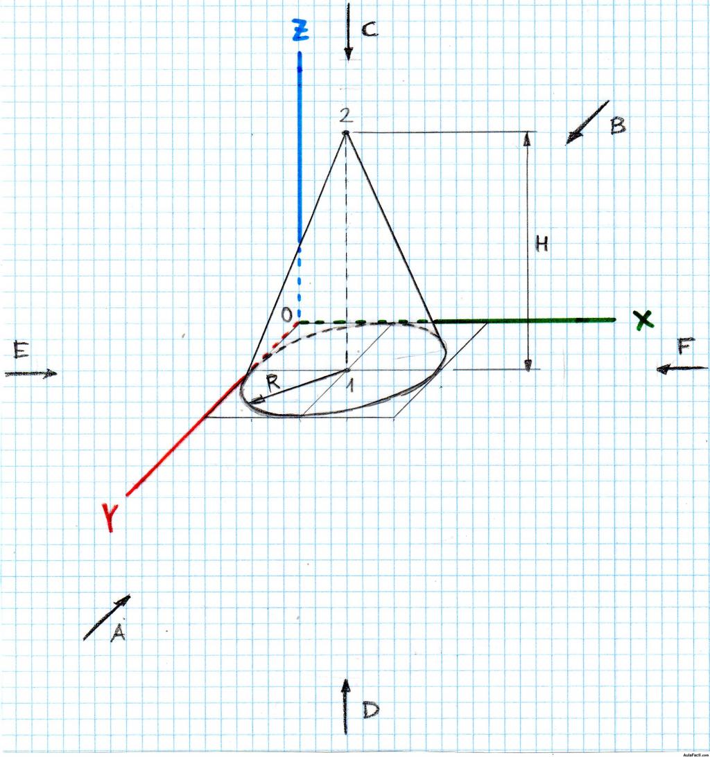
This approach allows you to assign a pitch from 0 to 90, where 0 means lying on screen and 90 means perpendicular to screen.
(Certainly you can assign 91.1 or 5566 or any good number. Currently the abs in the code wipe out all funny situations.)
Once you fix the pitch, the drawing code part will do some necessary calculations such as positions of the tangent points. Notice that while predefined arrow tips have some additional options such as open and harpoon, my tip does not implement them. I even use fill to get rid of line-width issue.


\documentclass[tikz,border=9]{standalone}
\usepgflibrary{arrows.meta}

\makeatletter

\pgfkeys{
  /pgf/arrow keys/.cd,
  pitch/.code={%
    \pgfmathsetmacro\pgfarrowpitch{#1}
    \pgfmathsetmacro\pgfarrowsinpitch{abs(sin(\pgfarrowpitch))}
    \pgfmathsetmacro\pgfarrowcospitch{abs(cos(\pgfarrowpitch))}
  },
}

\pgfdeclarearrow{
  name = Cone,
  defaults = {       % inherit from Kite
    length     = +3.6pt +5.4,
    width'     = +0pt +0.5,
    line width = +0pt 1 1,
    pitch      = +0, % lie on screen
  },
  cache = false,     % no need cache
  setup code = {},   % so no need setup
  drawing code = {   % but still need math
    % draw the base
    \pgfmathsetmacro\pgfarrowhalfwidth{.5\pgfarrowwidth}
    \pgfmathsetmacro\pgfarrowhalfwidthsin{\pgfarrowhalfwidth*\pgfarrowsinpitch}
    \pgfpathellipse{\pgfpointorigin}{\pgfqpoint{\pgfarrowhalfwidthsin pt}{0pt}}{\pgfqpoint{0pt}{\pgfarrowhalfwidth pt}}
    \pgfusepath{fill}
    % test if the cone part visible
    \pgfmathsetmacro\pgfarrowlengthcos{\pgfarrowlength*\pgfarrowcospitch}
    \pgfmathparse{\pgfarrowlengthcos>\pgfarrowhalfwidthsin}
    \ifnum\pgfmathresult=1
      % it is visible, so draw
      \pgfmathsetmacro\pgfarrowlengthtemp{\pgfarrowhalfwidthsin*\pgfarrowhalfwidthsin/\pgfarrowlengthcos}
      \pgfmathsetmacro\pgfarrowwidthtemp{\pgfarrowhalfwidth/\pgfarrowlengthcos*sqrt(\pgfarrowlengthcos*\pgfarrowlengthcos-\pgfarrowhalfwidthsin*\pgfarrowhalfwidthsin)}
      \pgfpathmoveto{\pgfqpoint{\pgfarrowlengthcos pt}{0pt}}
      \pgfpathlineto{\pgfqpoint{\pgfarrowlengthtemp pt}{ \pgfarrowwidthtemp pt}}
      \pgfpathlineto{\pgfqpoint{\pgfarrowlengthtemp pt}{-\pgfarrowwidthtemp pt}}
      \pgfpathclose
      \pgfusepath{fill}
    \fi
    \pgfpathmoveto{\pgfpointorigin}
  }
}


\begin{document}

\begin{tikzpicture}[line width=5]
    \draw[-{Cone          }](0,0,0)--(1,0,0);
    \draw[-{Cone          }](0,0,0)--(0,1,0);
    \draw[-{Cone[pitch=60]}](0,0,0)--(0,0,1);
    \path(2,0,0)(0,2,0)(0,0,2);
\end{tikzpicture}

\foreach\theta in{0,10,...,350}{
    \tikz[line width=5]\draw[-{Cone[pitch=\theta]}](-2,0)(2,0)(0,0)--({cos(\theta)},0);
}

\foreach\theta in{0,10,...,350}{
    \tikz[line width=5,opacity=.5]\draw[-{Cone[pitch=\theta]}](-2,0)(2,0)(0,0)--({cos(\theta)},0);
}

\end{document}
Update
I a wrote three tips Cone1, Cone2, and Cone3.
Cone1


It uses pitch like the Cone above except that it now checks if sin(pitch) is positive. If so, it presumes that the arrow is pointing to your eyes and hence add a white dot. (At the same time, cos(pitch) is mandatorily positive.)
Speaking of dots, it is hard to decide the correct size and the color of it. Currently Cone1 reads the setting in line width and fill a white circle of which the diameter is the width. This is a good idea since the line width is not used anywhere else but also a bad idea if you do care about code legibility.
Cone2

This tip accepts a tangent option by tangent={(1,2,3)} so that it can calculate the pitch (actually the sine and cosine of it).
The problem is, throughout the world of TikZ no one has ever cared about projections of 3D-vectors perpendicular to the screen. If we are lucky enough that the current projection to the screen is of orthogonal type, which is probably assigned by tikz-3dplot, then the projection perpendicular to the screen is well defined in mathematics manner up to a sign. (We cannot tell the difference between into screen and out of screen given the projection to the screen.)
Unfortunately in most cases if you assign x=, y=, and z= by hand it would not be a orthogonal projection.
Here I simply use a cross-product to calculate the missing projection subjected to the condition that the result will be correct if one uses tikz-3dplot to assign the projection.
More precisely, \tikz@scan@one@point is a command used in TikZ to parse the coordinates such as (1,2), (3:4), (A), or (5,6,7). When I write
\tikz@scan@one@point\pgfarrowtangenttosincos#1
and #1 is, say, (5,6,7), TikZ will end up with
\pgfarrowtangenttosincos{\pgfpointxyz{5}{6}{7}}
And then, according to the definition of \pgfarrowtangenttosincos, PGF will executes
\pgfpointxyz{5}{6}{7}
\tdplotcrossprod(\pgf@xx,\pgf@yx,\pgf@zx)(\pgf@xy,\pgf@yy,\pgf@zy)
Now
(\pgftemp@x,\pgftemp@y,\pgftemp@z) is (5,6,7).(\pgf@x,\pgf@y) is the projection of (5,6,7) on the screen.(\tdplotresx,\tdplotresy,\tdplotresz) is the result of cross product.
So
sqrt(\pgf@x*\pgf@x+\pgf@y*\pgf@y) is the length on the screen- inner product of
(\tdplotresx,\tdplotresy,\tdplotresz) and (\tdplotresx,\tdplotresy,\tdplotresz) is the length off the screen
- the root-sum-square of the above two is the length of the whole vector.
So
- sine is
a/c
- cosine is
b/c
After that everything works like Cone1.
Cone3

I hack \pgfpointxyz so that it buffers two recent 3D-coordinates. While the arrow tip is being drawn, I presume that the old, buffered coordinate is the end and the older, buffered coordinate is the start. So the tangent should be the difference of these two coordinate.
Code
\documentclass[tikz]{standalone}
\usepgflibrary{arrows.meta}
\usepackage{tikz-3dplot}
\begin{document}


\makeatletter

\pgfkeys{
  /pgf/arrow keys/.cd,
  pitch/.code={%
    \pgfmathsetmacro\pgfarrowpitch{#1}
    \pgfmathsetmacro\pgfarrowcospitch{abs(cos(\pgfarrowpitch))}
    \pgfmathsetmacro\pgfarrowsinpitch{    sin(\pgfarrowpitch)}
  }
}

\pgfdeclarearrow{
  name = Cone1,
  defaults = {       % inherit from Kite
    length     = +3.6pt +5.4,
    width'     = +0pt +0.5,
    line width = +0pt 1 1,
    pitch      = +0, % lie on screen
  },
  cache = false,     % no need cache
  setup code = {},   % so no need setup
  drawing code = {   % but still need math
    % draw the base
    \pgfmathsetmacro\pgfarrowhalfwidth{.5\pgfarrowwidth}
    \pgfmathsetmacro\pgfarrowhalfwidthsin{\pgfarrowhalfwidth*abs(\pgfarrowsinpitch)}
    \pgfpathellipse{\pgfpointorigin}{\pgfqpoint{\pgfarrowhalfwidthsin pt}{0pt}}{\pgfqpoint{0pt}{\pgfarrowhalfwidth pt}}
    \pgfusepath{fill}
    % test if the cone part visible
    \pgfmathsetmacro\pgfarrowlengthcos{\pgfarrowlength*\pgfarrowcospitch}
    \ifdim\pgfarrowlengthcos pt>\pgfarrowhalfwidthsin pt
      % it is visible, so draw
      \pgfmathsetmacro\pgfarrowlengthtemp{\pgfarrowhalfwidthsin*\pgfarrowhalfwidthsin/\pgfarrowlengthcos}
      \pgfmathsetmacro\pgfarrowwidthtemp{\pgfarrowhalfwidth/\pgfarrowlengthcos*sqrt(\pgfarrowlengthcos*\pgfarrowlengthcos-\pgfarrowhalfwidthsin*\pgfarrowhalfwidthsin)}
      \pgfpathmoveto{\pgfqpoint{\pgfarrowlengthcos pt}{0pt}}
      \pgfpathlineto{\pgfqpoint{\pgfarrowlengthtemp pt}{ \pgfarrowwidthtemp pt}}
      \pgfpathlineto{\pgfqpoint{\pgfarrowlengthtemp pt}{-\pgfarrowwidthtemp pt}}
      \pgfpathclose
      \pgfusepath{fill}
    \else
      % it is invisible, check in pointing your eye
      \ifdim\pgfarrowsinpitch pt>0pt
      \pgfpathcircle{\pgfqpoint{\pgfarrowlengthcos pt}{0pt}}{.5\pgfarrowlinewidth}
      \pgfsetcolor{white}
      \pgfusepath{fill}
      \fi
    \fi
    \pgfpathmoveto{\pgfpointorigin}
  }
}
%\begin{tikzpicture}[line width=5]
%   \draw[-{Cone1          }](0,0,0)--(1,0,0);
%   \draw[-{Cone1          }](0,0,0)--(0,1,0);
%   \draw[-{Cone1[pitch=60]}](0,0,0)--(0,0,1);
%   \path(3,0,0)(0,3,0)(0,0,3);
%\end{tikzpicture}
%\foreach\theta in{0,10,...,350}{
%   \tikz[line width=5]\draw[-{Cone1[width'=0 1,pitch=\theta]}](-2,-.5)(2,.5)(0,0)--({cos(\theta)},0);
%}
%\foreach\theta in{0,10,...,350}{
%   \tikz[line width=5,opacity=.5]\draw[-{Cone1[width'=0 1,pitch=\theta]}](-2,-.5)(2,.5)(0,0)--({cos(\theta)},0);
%}


\def\pgfarrowtangenttosincos#1{
    #1
    \tdplotcrossprod(\pgf@xx,\pgf@yx,\pgf@zx)(\pgf@xy,\pgf@yy,\pgf@zy)
    \pgfmathsetmacro\pgfarrowtangentxxyy{\pgf@x*\pgf@x+\pgf@y*\pgf@y}
    \pgfmathsetmacro\pgfarrowtangentxy{sqrt(\pgfarrowtangentxxyy)}
    \pgfmathsetmacro\pgfarrowtangentz{(\pgftemp@x*\tdplotresx+\pgftemp@y*\tdplotresy+\pgftemp@z*\tdplotresz)/72.27*2.54}
    %\message{^^J^^J(\tdplotresx,\tdplotresy,\tdplotresz)(\pgfarrowtangentxy,\pgfarrowtangentz)}\show\\
    \pgfmathsetmacro\pgfarrowtangentxyz{sqrt(\pgfarrowtangentxxyy+\pgfarrowtangentz*\pgfarrowtangentz)}
    \pgfmathsetmacro\pgfarrowcospitch{\pgfarrowtangentxy/\pgfarrowtangentxyz}
    \pgfmathsetmacro\pgfarrowsinpitch{\pgfarrowtangentz/\pgfarrowtangentxyz}
}
\pgfkeys{
  /pgf/arrow keys/.cd,
  tangent/.code={%
    \tikz@scan@one@point\pgfarrowtangenttosincos#1
  }
}
\pgfdeclarearrow{
  name = Cone2,
  defaults = {             % inherit from Kite
    length     = +3.6pt +5.4,
    width'     = +0pt +0.5,
    line width = +0pt 1 1,
    tangent    = {(1,0,0)} % lie on x-axis
  },
  cache = false,           % no need cache
  setup code = {},         % so no need setup
  drawing code = {         % but still need math
    % draw the base
    \pgfmathsetmacro\pgfarrowhalfwidth{.5\pgfarrowwidth}
    \pgfmathsetmacro\pgfarrowhalfwidthsin{\pgfarrowhalfwidth*abs(\pgfarrowsinpitch)}
    \pgfpathellipse{\pgfpointorigin}{\pgfqpoint{\pgfarrowhalfwidthsin pt}{0pt}}{\pgfqpoint{0pt}{\pgfarrowhalfwidth pt}}
    \pgfusepath{fill}
    % test if the cone part visible
    \pgfmathsetmacro\pgfarrowlengthcos{\pgfarrowlength*\pgfarrowcospitch}
    \ifdim\pgfarrowlengthcos pt>\pgfarrowhalfwidthsin pt
      % it is visible, so draw
      \pgfmathsetmacro\pgfarrowlengthtemp{\pgfarrowhalfwidthsin*\pgfarrowhalfwidthsin/\pgfarrowlengthcos}
      \pgfmathsetmacro\pgfarrowwidthtemp{\pgfarrowhalfwidth/\pgfarrowlengthcos*sqrt(\pgfarrowlengthcos*\pgfarrowlengthcos-\pgfarrowhalfwidthsin*\pgfarrowhalfwidthsin)}
      \pgfpathmoveto{\pgfqpoint{\pgfarrowlengthcos pt}{0pt}}
      \pgfpathlineto{\pgfqpoint{\pgfarrowlengthtemp pt}{ \pgfarrowwidthtemp pt}}
      \pgfpathlineto{\pgfqpoint{\pgfarrowlengthtemp pt}{-\pgfarrowwidthtemp pt}}
      \pgfpathclose
      \pgfusepath{fill}
    \else
      % it is invisible, check in pointing your eye
      \ifdim\pgfarrowsinpitch pt>0pt
      \pgfpathcircle{\pgfqpoint{\pgfarrowlengthcos pt}{0pt}}{.5\pgfarrowlinewidth}
      \pgfsetcolor{white}
      \pgfusepath{fill}
      \fi
    \fi
    \pgfpathmoveto{\pgfpointorigin}
  }
}
\tdplotsetmaincoords{70}{110}
\begin{tikzpicture}[line width=5,tdplot_main_coords]
    \draw[-{Cone2[tangent={(1,0,0)}]}](0,0,0)--(1,0,0)node[cyan]{X};
    \draw[-{Cone2[tangent={(0,1,0)}]}](0,0,0)--(0,1,0)node[cyan]{Y};
    \draw[-{Cone2[tangent={(0,0,1)}]}](0,0,0)--(0,0,1)node[cyan]{Z};
    \path(-2cm,-2cm)(2cm,2cm);
\end{tikzpicture}

\foreach\theta in{0,10,...,350}{
    \tdplotsetrotatedcoords{\theta}{30}{30}
    \tikz[line width=5,line cap=round,tdplot_rotated_coords]{
        \draw[-{Cone2[tangent={(1,0,0)}]}](0,0,0)--(1,0,0)node[cyan]{X};
        \draw[-{Cone2[tangent={(0,1,0)}]}](0,0,0)--(0,1,0)node[cyan]{Y};
        \draw[-{Cone2[tangent={(0,0,1)}]}](0,0,0)--(0,0,1)node[cyan]{Z};
        \path(-2cm,-2cm)(2cm,2cm);
    }
}


\def\pgfpointxyz#1#2#3{%
  \pgfmathparse{#1}%
  \let\pgftemp@x=\pgfmathresult%
  \pgfmathparse{#2}%
  \let\pgftemp@y=\pgfmathresult%
  \pgfmathparse{#3}%
  \let\pgftemp@z=\pgfmathresult%
  \pgf@x=\pgftemp@x\pgf@xx%
  \advance\pgf@x by \pgftemp@y\pgf@yx%
  \advance\pgf@x by \pgftemp@z\pgf@zx%
  \pgf@y=\pgftemp@x\pgf@xy%
  \advance\pgf@y by \pgftemp@y\pgf@yy%
  \advance\pgf@y by \pgftemp@z\pgf@zy%
  % ↑↑↑old definition↑↑↑ ↓↓↓new code↓↓↓
  \global\let\pgfolderpointx\pgfoldpointx
  \global\let\pgfolderpointy\pgfoldpointy
  \global\let\pgfolderpointz\pgfoldpointz
  \global\let\pgfoldpointx\pgftemp@x
  \global\let\pgfoldpointy\pgftemp@y
  \global\let\pgfoldpointz\pgftemp@z
}


\pgfdeclarearrow{
  name = Cone3,
  defaults = {             % inherit from Kite
    length     = +3.6pt +5.4,
    width'     = +0pt +0.5,
    line width = +0pt 1 1,
    tangent    = {(1,0,0)} % lie on x-axis
  },
  cache = false,           % no need cache
  setup code = {},         % so no need setup
  drawing code = {         % but still need math
    % calculate the tangent
    \pgfkeys{pgf/arrow keys/tangent={(\pgfoldpointx-\pgfolderpointx,\pgfoldpointy-\pgfolderpointy,\pgfoldpointz-\pgfolderpointz)}}
    % draw the base
    \pgfmathsetmacro\pgfarrowhalfwidth{.5\pgfarrowwidth}
    \pgfmathsetmacro\pgfarrowhalfwidthsin{\pgfarrowhalfwidth*abs(\pgfarrowsinpitch)}
    \pgfpathellipse{\pgfpointorigin}{\pgfqpoint{\pgfarrowhalfwidthsin pt}{0pt}}{\pgfqpoint{0pt}{\pgfarrowhalfwidth pt}}
    \pgfusepath{fill}
    % test if the cone part visible
    \pgfmathsetmacro\pgfarrowlengthcos{\pgfarrowlength*\pgfarrowcospitch}
    \ifdim\pgfarrowlengthcos pt>\pgfarrowhalfwidthsin pt
      % it is visible, so draw
      \pgfmathsetmacro\pgfarrowlengthtemp{\pgfarrowhalfwidthsin*\pgfarrowhalfwidthsin/\pgfarrowlengthcos}
      \pgfmathsetmacro\pgfarrowwidthtemp{\pgfarrowhalfwidth/\pgfarrowlengthcos*sqrt(\pgfarrowlengthcos*\pgfarrowlengthcos-\pgfarrowhalfwidthsin*\pgfarrowhalfwidthsin)}
      \pgfpathmoveto{\pgfqpoint{\pgfarrowlengthcos pt}{0pt}}
      \pgfpathlineto{\pgfqpoint{\pgfarrowlengthtemp pt}{ \pgfarrowwidthtemp pt}}
      \pgfpathlineto{\pgfqpoint{\pgfarrowlengthtemp pt}{-\pgfarrowwidthtemp pt}}
      \pgfpathclose
      \pgfusepath{fill}
    \else
      % it is invisible, check in pointing your eye
      \ifdim\pgfarrowsinpitch pt>0pt
      \pgfpathcircle{\pgfqpoint{\pgfarrowlengthcos pt}{0pt}}{.5\pgfarrowlinewidth}
      \pgfsetcolor{white}
      \pgfusepath{fill}
      \fi
    \fi
    \pgfpathmoveto{\pgfpointorigin}
  }
}
\tdplotsetmaincoords{70}{110}
\begin{tikzpicture}[line width=5,tdplot_main_coords]
    \draw[-{Cone2[tangent={(1,0,0)}]}](0,0,0)--(1,0,0)node[cyan]{X};
    \draw[-{Cone2[tangent={(0,1,0)}]}](0,0,0)--(0,1,0)node[cyan]{Y};
    \draw[-{Cone2[tangent={(0,0,1)}]}](0,0,0)--(0,0,1)node[cyan]{Z};
    \path(-2cm,-2cm)(2cm,2cm);
\end{tikzpicture}

\foreach\theta in{0,5,...,355}{
    \tdplotsetrotatedcoords{\theta}{2*\theta}{3*\theta}
    \tikz[line width=5,line cap=round,tdplot_rotated_coords]{
        \draw[-Cone3](0,0,0)--(1,0,0)node[cyan]{X};
        \draw[-Cone3](0,0,0)--(0,1,0)node[cyan]{Y};
        \draw[-Cone3](0,0,0)--(0,0,1)node[cyan]{Z};
        \path(-2cm,-2cm)(2cm,2cm);
    }
}


\end{document}


>={3D[blah,blah,blah]}and then get different arrows for each line so when you look at it the realism is higher. – Manuel Sep 12 '15 at 17:51bend). Since TikZ does not define 3D bezier curve, it cannot calculated the tangent line in space and thus draw the arrow accordingly. – Symbol 1 Sep 14 '15 at 08:55>=3D(unless someone hacks the way three dimensional coordinates are parsed, to save for later the three dimensions). Any other user interface would be okey, e.g.,\spacearrow{⟨arrow options⟩}{⟨origin⟩}{⟨end⟩};. My problem with pgf/TikZ is that I never understood the basics, so I can't dive into the source to find this critical parts (I don't even know how the files are organized). – Manuel Sep 14 '15 at 09:33