13

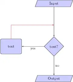
I have a flowchart as shown in the left diagram. I want to draw a line from a node to an edge as shown in the right diagram. See:

Sample

How can I do that?

\documentclass{article} 
\usepackage{tikz}
\begin{document}
\usetikzlibrary{shapes,arrows}

% Define block styles
\tikzstyle{io} = [trapezium,trapezium left angle=70,trapezium right angle=-70,minimum height=0.6cm, draw, fill=blue!20, 
text width=4.5em, text badly centered, node distance=3cm, inner sep=0pt]
\tikzstyle{decision} = [diamond, draw, fill=blue!20, 
text width=4.5em, text badly centered, node distance=4cm, inner sep=0pt]
\tikzstyle{block} = [rectangle, draw, fill=blue!20, 
text width=5em, text centered, rounded corners, minimum height=4em]
\tikzstyle{line} = [draw, -latex']
\tikzstyle{cloud} = [draw, ellipse,fill=red!20, node distance=3cm,
minimum height=2em]

\begin{tikzpicture}[node distance = 2cm, auto]
% Place nodes
\node [io] (init) {Input};
\node [decision, below of=init] (identify) {text?};
\node [block, left of=identify,xshift=-2cm] (process) {text};
\node [io, below of=identify, node distance=3cm] (stop) {Output};
% Draw edges  
\path [line] (init) -- node {}(identify);
\path [line] (identify) -- node {no}(stop);
\path [line] (identify) -- node {yes}(process);
\end{tikzpicture}
\end{document}
JLDiaz
  • 55,732

2 Answers2

12

Use |- syntax for the corner and coordinate interpolation for the point in the middle of the two nodes to which the arrow points. This require tikz library calc.

\documentclass{article}
\usepackage{tikz}
\begin{document}
\usetikzlibrary{shapes,arrows,calc}

% Define block styles
\tikzstyle{io} = [trapezium,trapezium left angle=70,trapezium right angle=-70,minimum height=0.6cm, draw, fill=blue!20, 
text width=4.5em, text badly centered, node distance=3cm, inner sep=0pt]
\tikzstyle{decision} = [diamond, draw, fill=blue!20, 
text width=4.5em, text badly centered, node distance=4cm, inner sep=0pt]
\tikzstyle{block} = [rectangle, draw, fill=blue!20, 
text width=5em, text centered, rounded corners, minimum height=4em]
\tikzstyle{line} = [draw, -latex']
\tikzstyle{cloud} = [draw, ellipse,fill=red!20, node distance=3cm,
minimum height=2em]

\begin{tikzpicture}[node distance = 2cm, auto]
% Place nodes
\node [io] (init) {Input};
\node [decision, below of=init] (identify) {text?};
\node [block, left of=identify,xshift=-2cm] (process) {text};
\node [io, below of=identify, node distance=3cm] (stop) {Output};
% Draw edges  
\path [line] (init) -- node {}(identify);
\path [line] (identify) -- node {no}(stop);
\path [line] (identify) -- node {yes}(process);
\path [line, red] (process) |- ($(init)!.5!(identify)$);
\end{tikzpicture}
\end{document}

Result

JLDiaz
  • 55,732
4

An alternative option to JLDiaz answer would be the use of |- syntax and an auxiliary node. This way you don't need calc library.

As you already used in your code, command

\path [line] (identify) -- node {no}(stop); 

places a node in the mid point between node identify and stop. If you gives a name to the node you can use it afterwards as a reference point.

\path [line] (identify) -- node (no) {no}(stop);

and with [pos=...] syntax you can move the node along the path

\path [line] (identify) -- node[pos=0.3] (no) {no}(stop);

You need an empty node alogn the path (init) -- (identify) something like

\path[line] (init) -- node (aux) {} (identify);

The complete code with this options looks like:

\documentclass{article}
\usepackage{tikz}
\begin{document}
\usetikzlibrary{shapes,arrows}

% Define block styles
\tikzstyle{io} = [trapezium,trapezium left angle=70,trapezium right angle=-70,minimum height=0.6cm, draw, fill=blue!20, 
text width=4.5em, text badly centered, node distance=3cm, inner sep=0pt]
\tikzstyle{decision} = [diamond, draw, fill=blue!20, 
text width=4.5em, text badly centered, node distance=4cm, inner sep=0pt]
\tikzstyle{block} = [rectangle, draw, fill=blue!20, 
text width=5em, text centered, rounded corners, minimum height=4em]
\tikzstyle{line} = [draw, -latex']
\tikzstyle{cloud} = [draw, ellipse,fill=red!20, node distance=3cm,
minimum height=2em]

\begin{tikzpicture}[node distance = 2cm, auto]
% Place nodes
\node [io] (init) {Input};
\node [decision, below of=init] (identify) {text?};
\node [block, left of=identify,xshift=-2cm] (process) {text};
\node [io, below of=identify, node distance=3cm] (stop) {Output};
% Draw edges  
\path [line] (init) -- node[pos=.3] (aux) {}(identify);
\path [line] (identify) -- node (no) {no}(stop);
\path [line] (identify) -- node {yes}(process);
\path [line, red] (process) |- (aux);
\path [line, red] (process) |- (no);
\end{tikzpicture}
\end{document}

and the result

enter image description here

Ignasi
  • 136,588