I'm afraid this will require some explanation. I'm sorry, this will be a long read but I hope it's an interesting conundrum. If anyone reading this isn't familiar with NASA's PRANDTL wing research, Al Bowers' main paper is here: https://ntrs.nasa.gov/citations/20160003578
As a brief summary, Bowers and his team surmise that a Bell-Shaped Lift Distribution (BSLD) rather than the ubiquitous elliptical one, combined with very pronounced wing twist, can produce 'proverse yaw' which they explain as a portion of the outer wing producing a lift vector tilted forward. They then design a series of gliders based on this theory which are flying wings, with no vertical stabiliser. These gliders are tested, and it is found that they can in fact execute coordinated turns without a rudder or other independent yaw control surface.
Then, in answering this question: Why isn't the bell distribution used? Peter Kämpf's excellent answer suggested that in fact at most angles of attack (I.E. except near stall) the BSLD is actually producing negative lift at the tips, which seemed to agree with the stall analysis done of the design: https://ntrs.nasa.gov/citations/20180006832 in tandem with another paper outlining the model validation tests: https://ntrs.nasa.gov/citations/20210014683 this perfectly well explains the proverse yaw and controllability without any controversy.
That seemed to be that, however, keen to examine the wing further, particularly in the assertion by Bowers and his team that the flying wing would yaw out of a slip angle back into the prevailing wind direction, which I still do not understand, I did some CFD. I downloaded a CAD model from the internet which was shared by the team, stitched it, stuck it into simscale with no slip angle, and no adjustment to angle of attack from the CAD file, and did a few quick check runs to see if it all worked nicely. It did, but the results seem to me pretty startling... my question is, looking at the CFD below, what on earth is going on?! The simulation can be found here in case you wish to interrogate it yourself: https://www.simscale.com/projects/vh23138/prandtl-d_incomp-/ it's an incompressible simulation with potential flow initialisation at 13.7m/s flight velocity (45ft/s as per above papers).
CAD file tip geometry: this is the CAD file in Fusion 360, the wingtip foil is symmetrical, and at an AoA of around -2.2 to the flow axis

SimScale wake: There is clearly upwash along the outboard region of the wing,

SimScale pressure slices: a) slice taken just above the port wingtip, location shown in second image,

 b) slice taken just below the port wingtip, location shown in second image

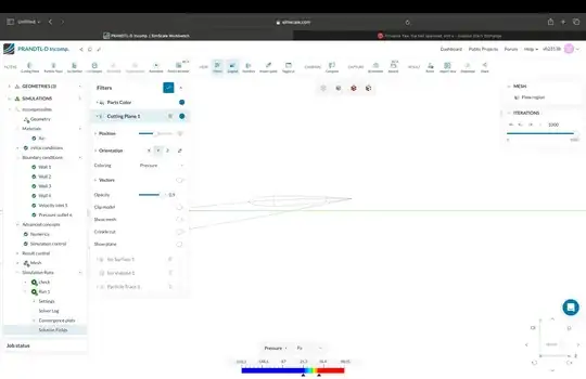
SimScale wingtip pressure distribution: this is a slice taken as a cross-section through the wingtip airfoil, showing a sort of chord wise pressure distribution as far outboard on the starboard wing as I could get without there being virtually no airfoil there, the location is shown in the second image (sorry, it's hard to see the wing wireframe).


So my question: 1. shows symmetrical airfoil at -AoA, 2. shows upwash at that foil, 3. appears to show modest lift production, or at least, a marked lack of clear downforce. Which leads to the question: How?! currently the best I can assume is this a 3D aerodynamic effect produced by the flow field around the whole wing, but that isn't an answer...
