2

You can discard the images I have uploaded and can simply use some camera angles of your choice to render depth maps of a 3D shape and then fuse the rendered depth maps to recover the underlying 3D shape

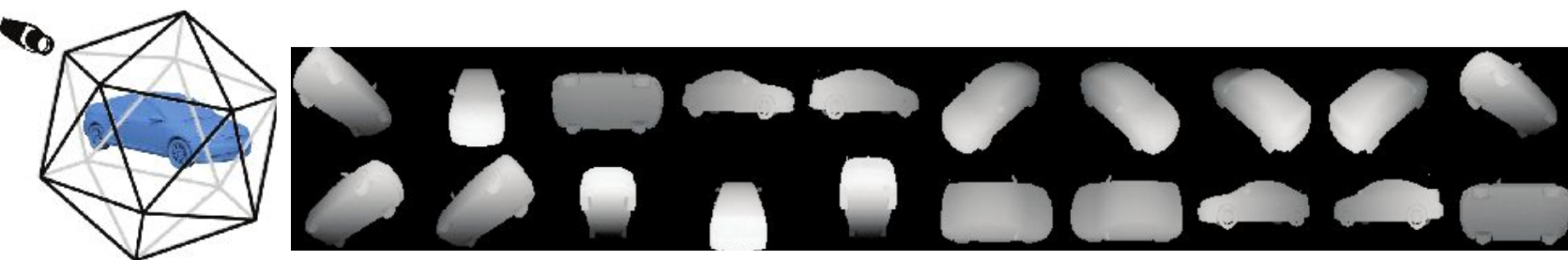
We recently published a paper on 3D shape generation in a computer vision conference (CVPR). My co-author wrote the code (in C++ and using OpenCV) for fusing the depth maps and getting the final 3D shapes from the produced multi-view outputs. The inputs to the code he wrote is 20 depth maps, ground-truth camera angles (posted below) and the distance from the centroid of the shapes to the camera (distance to the shape centroid=1.5 on a sphere). The centroid of shapes are calculated as follow:

First, the centers of faces (triangle) of a mesh centroid of a mesh is calculated. Then the faces areas are computed. The new centroid is the average of the mesh faces' centers, weighted by their area.

Here some people have written algorithms on how to compute the centroids.

Unfortunately my friend is not available to help me on this and I cannot use OpenCV and C++ for this new project that I'm beginning to work on. So any help would be appreciated. My goal is to write some code using Blender's Python API instead of using my co-author's C++ code to do the same thing. But before I move on, I wonder if Blender has some built-in functions that can generate the final 3D shape given rendered depth maps of that shape, camera angles and the distance to the camera? If not, can anyone give me some ideas on how I should do that and give me a code sample for it?

Here I have uploaded a set of rendered depth maps a headphone's 3D shape that you can use for backward projection (reconstructing the 3D shape). And if you prefer to start with a 3D shape directly, here you can download a 3D shape of a different headphone we used in our work before. You can render depth maps the 3D shape using the camera angles posted below.

FYI, here is my co-author's high-level description on how his approach works:

In the final step, all depth maps are projected back to the 3D space to create the final rendering. We reconstruct 3D shapes from multi-view silhouettes and depth maps by first generating a 3D point cloud from each depth image with its corresponding camera setting (x, y, z coordinates). The union of these point clouds from all views can be seen as an initial estimation of the shape.

And here are the camera angles we used for doing the rendering in the first place:

-0.57735  -0.57735  0.57735
0.934172  0.356822  0
0.934172  -0.356822  0
-0.934172  0.356822  0
-0.934172  -0.356822  0
0  0.934172  0.356822
0  0.934172  -0.356822
0.356822  0  -0.934172
-0.356822  0  -0.934172
0  -0.934172  -0.356822
0  -0.934172  0.356822
0.356822  0  0.934172
-0.356822  0  0.934172
0.57735  0.57735  -0.57735
0.57735  0.57735  0.57735
-0.57735  0.57735  -0.57735
-0.57735  0.57735  0.57735
0.57735  -0.57735  -0.57735
0.57735  -0.57735  0.57735
-0.57735  -0.57735  -0.57735
Amir
  • 3,074
  • 2
  • 29
  • 55
  • 2
    That second link doesn't go anywhere. Preferably add the image(s) into the post directly. See: https://meta.stackexchange.com/questions/75491/how-to-upload-an-image-to-a-post – Ray Mairlot Feb 07 '18 at 16:57
  • @RayMairlot Sorry, I just fixed it. There are 20 depth maps so I did not want to attach them one by one here. Also because the compression methods are applied on uploaded images and you cannot use them in raw formats I have (probably) – Amir Feb 07 '18 at 18:13
  • @Amir are these the angles in correspondence to the sequence of the same images? – Rick Riggs Feb 07 '18 at 21:51
  • Yes Rick. I also uploaded an .obj file we used for rendering. The link is on the bottom of my post. – Amir Feb 07 '18 at 21:55
  • @Amir I think your second image must be rotated 180° on its own normal. Just positioning the first two images is showing this conflict. Is the original code doing this to the output? Also do you happen to know camera distance from the subject? – Rick Riggs Feb 07 '18 at 22:34
  • I learned that the distance to the camera is computed using a method I described here and it's not fixed ... – Amir Feb 08 '18 at 02:43
  • @RickRiggs Sorry I was mistaken. The distance of the camera is actually fixed since all shapes in our dataset are centered at (0, 0, 0). The camera distance to (0, 0, 0) is 1.5 and the camera coordinates are what you can see in my post. Would you give it another try to see if you can make the 3D shape? – Amir Feb 11 '18 at 17:25
  • @Amir So these are coordinates and not angles? I will give it another shot, based on the following post – Rick Riggs Feb 11 '18 at 20:21
  • Yes they are coordinates not angles. Given these coordinates and the center of focus (0, 0, 0) you should be able to compute the rotation matrix (for camera pose) while rendering. You can also use this rotation matrix and the resultant Euler angles when doing backward projection (obtaining the 3D shape from the depth maps) if you need too (which I don't think you need the Euler angles when doing backward projection) – Amir Feb 11 '18 at 20:30
  • @RickRiggs Hi Rick. I wonder, did you get a chance to take another look at this? Smooth continuation of my work is kind of dependent on this. Really appreciate your efforts in advance. – Amir Feb 17 '18 at 03:31
  • @Amir I did, and I found it to still not relationally project that well from those coordinates given. Something about them feels off, and I'm not sure if it is camera distortion, color space (middle gray + falloff greyscale bounds), coordinate space assignment differences, perspective occlusion etc., but it does seem a bit more difficult than I had originally imagined it being. – Rick Riggs Feb 17 '18 at 03:37

1 Answers1

2

After looking at the following image from your paper, it seems to me as if your image is basically a sprite map, so I propose the following workflow to get you there.

Proposed Workflow:

I'm certain that you could mimic the polyhedron shape in blender to set active planes (viewports) on programatically, and use an UV coordinate mapping per sprite location to get a depth map per the corresponding camera location/angle (position).

Set up a highly subdivided plane for each view, then attach the Displacement Modifier to it, along with a custom UV layout to the sprite sheet that corresponds with the appropriate viewpoint.

I would then add a global driver to attempt to control the displacement modifier strength per projection, and when they get close to each other...

Apply the modifier, Join the objects together, and remove duplicate verts.


Uploaded a Video

Rick Riggs
  • 4,623
  • 14
  • 30
  • Since your update... I may be mistaken as to the format of sprite image versus individual images, so in that case, just create a material per texture, and UV unwrap to each one, everything else would be the same approach. – Rick Riggs Feb 07 '18 at 18:19
  • Sorry this is a bit too high-level for me since I am not an expert in Blender. But I noticed that you are talking about rendering. However, I am talking about projecting back the already rendered views to get the underlying 3D Shape. Do you have a solution for that? – Amir Feb 07 '18 at 18:34
  • Using the code my co-author has written, I can use the uploaded depth maps and get the underlying 3D Shapes. – Amir Feb 07 '18 at 18:35
  • @Amir if your last comment is meant a question, then yes you can. I will try and give an example of the answer I have provided once I am able to put some time into it. – Rick Riggs Feb 07 '18 at 18:38
  • No that was not a question. I basically mean I feel you did not get the question I have asked. The goal is not to render, is to produce 3D. – Amir Feb 07 '18 at 18:45
  • @Amir that was my goal as well, after that you can do whatever you want to with the object. – Rick Riggs Feb 07 '18 at 18:51
  • Sorry I did not get that from your post maybe because I'm not able to follow well. I wonder, are you able to elaborate more or even better, provide some sample code in Python for that? – Amir Feb 07 '18 at 19:34
  • @Amir I uploaded an overview video to show the basics of the described workflow. – Rick Riggs Feb 07 '18 at 21:02
  • Thank you for all the efforts. It seems promising and indeed very interesting. Do you think it would be possible for you to make a short video on how the angles could be taken into account? I have updated my post and posted the angles we used when doing the original rendering. Btw: if I can use a similar approach to what you proposed here and my new project works out, I will definitely acknowledge you in our paper. If possible, could you please send me an email as well? Myt email can be found in the paper. Thanks again – Amir Feb 07 '18 at 21:43