
How to.create mesh in the base of a bracket without harm ing the brackets base dimensions
k
How to.create mesh in the base of a bracket without harm ing the brackets base dimensions
k
Import your models (or design from scratch) your bracket objects into a .blend file. Each bracket should be a separate Blender object. You can name the brackets whatever you like. I recommend some syntax which let's you know the intended tooth, and some of the clinical parameters of the bracket's prescription. Eg, "UR3_tip11_tq0" for an Upper Right Canine, with 11 degree tip and 0 degree torque.
Orientation of the Bracket Correct orientation of the bracket is critical to the convenience .
The 'Z' axis should point toward the facial aspect of the bracket
The local positive 'Y' axis should point toward the incisal, and be perpendicular to the wire slot, NOT aligned with the vertical alignment slot. This is important for the bracket being displayed correctly when first imported.
The 'X' axis should be aligned with the horizontal wire slot, the positive direction does not matter, and is determined by #1, and #2 above.
The local object origin, should be in the middle of the bracket, on the surface which touches the tooth.
Here is an example of the Upper Right Canine (first image) and the lower right canine (second image). A few things are important to notice. The positive Z-axis (blue arrow) points outward to the facial in both situations. The positive Y-axis (green arrow) points toward the incisal, which is down in the first image and up in the 2nd image. The X-axis (red arrow) is parallel with the wire slot, but can point in either direction (left in first image, right in second) based on the requirements of the first two constraints. Both these images show the local coordinate transform selected (the white arrow).
Assigning Custom Properties Custom properties allow to display clinically meaningful visual guides to placing the bracket with respect to the bracket's prescription (eg. tip, torque, in/out etc'). Currently, only prescribed tip has any effect on how the visual aids are displayed while using the orthodontic bracket placement tools.
Adding a custom property There are 2 ways a custom property can be added to a bracket. The easiest way is to add a property via the object tab of the properties panel. The "Custom Properties" panel is at the very bottom of that tab, you may need to scroll down. You can "Add Custom Property" which will create a blank property that you can edit the name and value of. From here you must add the following custom properties to your brackets for the visual aids to display correctly.
quadrant - must be lower case, can be UR, UL, LL, LR, 1, 2, 3, 4 tip - any positive or negative number, in degrees bracket_gauge - the length of the virtual bracket placement gauge Other properties will be supported in the future, and you can add any information you want to it! Brand, author, system etc.
Using python to automate Going through and adding and editing these properties one by one can be time consuming. The following simple script will at least add the custom data properties, which you can then edit in the properties panel above.
for ob in bpy.data.objects: if not ob.get('tip'): ob['tip'] = 0.0 if not ob.get('torque'): ob['torque'] = 0.0


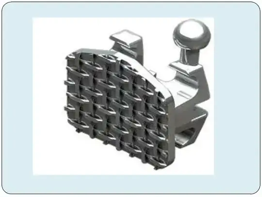
Then for base create chain like structures and copy pate it for planner base surface:
