When the upper and lower rafters are of equal size, the static load balance requires that the slope of the lower rafter S2 should be 3 times more than the slope of the upper rafter S1. Then the force of the upper rafter pushing the joint point outward will be exactly equal to the force of the lower rafter pushing the joint inward.
This is the case of 30 deg and 60 deg slopes of upper and lower rafter,
which gives the height to half width ratio of unity and the gambrel fits
a semicircle. The closest rational number approximation of slopes for these angles is 7/12 and 21/12 (corresponding to 1/sqrt(3) and sqrt(3)).
If you desire different height to width ratios, you can change the slope
of the upper rafter, and again in order to have the static load balance
the slope of the lower rafter should be 3 times more.
In general, for the rafters of different length L1, L2 (and hence mass), the static load balance is satisfied when slopes S1, S2 are given by the formula
S2 = S1 * (2 + L2/L1)
Gambrel Roof Static Stress Analysis

Fig 1. Sketch: forces acting on gambrel roof segments.
Momentum balance for each rafter along x and y axes (see Fig 1).
Stresses at the joints are opposite, no torques.
Y0 = 0
no ridge support
X0 is the horizontal force at the ridge.
X1 = X0
x-momentum balance for rafter 1
Y1 = m1*g
y-momentum balance for rafter 1 of mass m1: vertical force at joint 1 = weight of rafter 1
X2 = X1
x-momentum balance for rafter 2:
horizontal force at face plate = horizontal force at the ridge
Y2 = Y1 + m2*g
y-momentum balance for rafter 2 of mass m2: vertical force at face plate = total weight of rafter 1 and 2
Angular momentum balance for each rafter with respect to center of each rafter. The lengths of rafters are arbitrary, they cancel because the balance is with respect to center.
for rafter 1:
X0*sin(A1) + X1*sin(A1) = Y1*cos(A1)
for rafter 2:
X1*sin(A2) + X2*sin(A2) = Y1*cos(A2) + Y2*cos(A2)
where A1, A2 are the slope angles. Substituting expressions for X1, Y1, X2, Y2 from momentum balance we get for the slopes of rafters
S1 = tan(A1) = ½ * X0 / (m1*g)
S2 = tan(A2) = ½ * X0 / (2*m1*g+m2*g)
The system is overdetermined. The angles cannot be specified arbitrarily. In order for the torque at joint 1 (between the two rafters) to vanish the following condition must be satisfied
S2 = S1 * (2*m1+m2) / m1
(Eq 1)
which physically means that the weight of upper rafter pushing the joint outward is in balance with the weight of lower rafter pushing the joint inward.
For rafters (roof segments) of equal mass (length) the condition simplifies to
S2 = 3 * S1 or tan(A2) = 3 * tan(A1)
(Eq 2)
This does not determine the gambrel configuration yet. By varying the slopes (subject to the above restriction) we can change the height (H) to half width (W) ratio of the roof:
H = L1 * sin(A1) + L2 * sin(A2)
W = L1 * cos(A1) + L2 * cos(A2)
where L1, L2 are the rafter lengths.
For equal length and mass rafters, in terms of the upper rafter slope S1
H/W = (sin(arctan(S1)) + sin(arctan(3*S1))) / (cos(arctan(S1)) + cos(arctan(3*S1)))
(Eq 3)
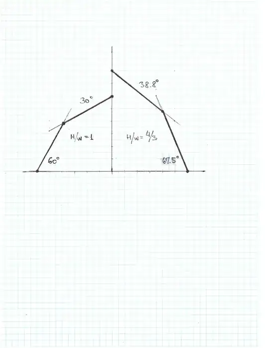
Fig 2. Balanced (S2=3*S1) “ideal” roof with H/W=1 (left) and with H/W=4/3 (right).
The “ideal” roof configuration is (L1=L2) with the height to half width ratio of one (Fig. 2, left)
A1 = 30 deg, S1 = 1/sqrt(3) = 0.577350 , A2 = 60 deg, S2 = sqrt(3) = 1.732050, H/W = 1
The closest carpenter’s approximation to that is S1 = 7/12 = 0.583333, S2 = 3*S1 = 21/12 = 1.75, hence A1 = 30.25 deg, A2 = 60.25 deg, H/W = 1.008968.
To make roof higher, for example, with H/W = 4/3 (see Fig. 2 right), S1 = 0.8036585 (according to Eq~3), S2 = 3*S2 = 2.410975, A1 = 38.7874 deg, A2 = 67.4728 deg.
The above analysis considers stresses caused by the gambrel roof its own weight only. The snow load, ridge support or other reinforcements are not included. This is purely an academic exercise and is not a substitute for a certified building plan.