-3

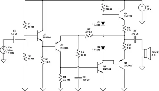
I have to design an audio amplifier to drive 500 mW 8 ohm load. I used two SMD transistors (BCP54 NPN and BCP51 PNP) and three BC847Bs, one to drive the BCP transistors, one for voltage gain, and one for current gain.

enter image description here

I calculated that there must be 2.8 V and -2.8 V swings on both transistors to achieve maximum 500 mW power. V=sqroot(PR)=sqroot(500mW8)*sqroot(2) = 2.8 V

I decided that at one peak there will need to be 9V on R3 transistor, on another peak there will need to be 3.4 V on R3 transistor. According to that I calculated values for resistors of Q3, Q4 and Q5 transistors. I want input impedance to be 50 kohm and voltage gain of 100. The problem is that it doesn't work. What have I done wrong?

winny
  • 14,707
  • 6
  • 46
  • 66
Pavle Hribar
  • 193
  • 1
  • 8
  • 6
    Maybe you should define what "it does not work" means. What does it do then if it does not do what you expect? Also related, how do you think Q3 can work without proper DC bias on base? – Justme Mar 14 '22 at 01:14
  • There are just weird signals of few nV if I monitor 8 ohm load with oscilosope. Q3 is supposed to get bias by Q4 – Pavle Hribar Mar 14 '22 at 01:19
  • 2
    your schematic does not show an 8 ohm load ... in fact, it shows no output connection – jsotola Mar 14 '22 at 01:47
  • How does Q3 get biased from Q4 when you put a capacitor between them? "Biasing" typically requires a DC voltage, which the capacitor blocks... – brhans Mar 14 '22 at 01:57
  • 1
    We are not here to do your homework for you. You need to show us that you have made a substantial effort to solve this yourself. – Elliot Alderson Mar 14 '22 at 02:09
  • @PavleHribar A class-A design is easier to implement. It's wasteful in terms of power. But I don't see a specification that requires class-AB. So I'd just go class-A for this. Your peak to peak output swing is about 5.7 V, which is readily achieved with a 12 VDC rail and ground in class-A. Use an output pair of D44H11 devices so as to dissipate enough. Two more BJTs, total of 4, and you are done. See here and here, for example. – jonk Mar 14 '22 at 05:18
  • @brhans Oh wait, that capacitor was not supposed to be there. I was just trying some different things in a sim, and forgot removing it – Pavle Hribar Mar 14 '22 at 06:14
  • @jonk I know how to make an A class amp already, am trying to do AB now – Pavle Hribar Mar 14 '22 at 06:15
  • @jsotola The connection is there between both emitters of C1 and C2. I will edit – Pavle Hribar Mar 14 '22 at 06:26
  • Capacitor serial with R8 would be interesting ? – Antonio51 Mar 14 '22 at 07:52

2 Answers2

2

Two obvious things:-

  1. The load is drawing DC current from the output. You need to connect the speaker through a capacitor.

  2. You have two voltage gain stages with local feedback producing a gain of 'about' 100, but no DC stabilization. The bias point will be hard to adjust correctly and drift horribly.

Another problem is you have no overall negative feedback, so the amplifier will probably have high distortion. To fix this you can apply negative feedback with a resistor from the output to the Emitter of Q4.

If you make Q4 a PNP type then you can apply 100% DC feedback for excellent DC stability, then bypass the Emitter through a resistor and capacitor to ground to set the AC gain.

The circuit looks like this:-

schematic

simulate this circuit – Schematic created using CircuitLab

Bruce Abbott
  • 56,322
  • 1
  • 48
  • 93
  • Any reason you didn't bootstrap R8 to turn it into a constant current source? – jonk Mar 15 '22 at 21:56
  • @jonk I just made the minimum changes necessary to get it working. Didn't want to complicate the circuit - it took long enough just to draw that one! (Internet has been very bad here over the last few days - don't know why.) He only wants 0.5W output into 8 ohms, which shouldn't need bootstrapping on a 12V supply. – Bruce Abbott Mar 16 '22 at 02:15
  • It doesn't add any parts. It just uses the output capacitor in a slightly different topology by repositioning the speaker connections. (I'd do it just because it allows me to put more of the circuit under management.) I was just curious, is all. Thanks. – jonk Mar 16 '22 at 02:31
  • @jonk to do it with no more parts you have to connect the speaker to +ve supply instead of ground. Otherwise you need 2 more parts like this:- https://electronics.stackexchange.com/questions/539546/bootstrap-in-power-amplifier Bootstrapping is a good idea, but if I put that in the circuit I would have to explain how it worked. – Bruce Abbott Mar 16 '22 at 21:23
  • Yeah. I'd tie the speaker high. Just walk around the loop to see a constant voltage (nearly) across R8. It's not that horrible to explain. :) – jonk Mar 17 '22 at 02:45
0

For a good design, choose a proved one.

Make a dynamic DC analysis to fix the quiet point.
Make a transient analysis to see if Qp is ok, with signal i.e. 1 kHz, some mV, output with no "distortion".
Then, if all is "good", make a AC analysis, to fix bandwidth (capacitors).
In fine, check distortion (harmonic analysis).

winny
  • 14,707
  • 6
  • 46
  • 66
Antonio51
  • 13,128
  • 1
  • 7
  • 22