18

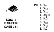
Several ICs are manufactured in packages with more pins than it supports. For example, the LM317 in an SO8 package has 4 VOUT pins and 2 N/C (no connection) pins. I often want to run traces through N/C pins to ease routing, but wonder if it would make them give up the ghost. If it exists, what is the standard or rule by which manufacturers follow concerning the electrical characteristics of N/C pins? Or do I have to scour the datasheet / do my own testing every time?

LM317 SO8 pinout

Glorfindel
  • 1,245
  • 3
  • 15
  • 20
tyblu
  • 8,207
  • 6
  • 41
  • 70

4 Answers4

16

It's a grey area. Some manufacturers tell you that's used for calibrating. Some manufacturers even will tell that you that certain pin has a function, only used by them for calibrating. Some tell you only not to connect it, or just say it's an unconnected pin.. You can't know for sure. The datasheet is information the manufacturer want to tell to you about using the device, but it might not be everything.

I recommended you do not connect them. If you get some generic IC from a different manufacturer or even batch the behaviour might be different. If you're engineering a project, you don't want to throw in unpredictability. You would have to test every single batch before you're going to use that particular batch. It depends on whatever you want to do that.

Hans
  • 7,277
  • 1
  • 26
  • 37
12

Normally "n.c." means that the pin is not connected to the die, and you should be safe running a trace over it. In some rare occasions I've read "n.c. DO NOT CONNECT", which rises the question why I shouldn't, if it's not connected internally anyway. In any case I expect the datasheet to mention it expressly when I shouldn't connect to the pin.

One example is pin 4 on the LP2981. Texas Instruments says "Pin 4 (NC) must be left open. Do not connect anything to this pin", without further explanation. National specifies: "Post package trim. **do not** connect to this pin". So the pin seems to be connected as expected, otherwise it would be safe to connect. In this case "not connected" should be read as 'no end user connection". Both manufacturers indicate clearly not to connect.

stevenvh
  • 145,832
  • 21
  • 457
  • 668
  • 1
    Apparently "post package trim" is used to adjust a bandgap reference that has been shifted by packaging. (See 1, 2.) Thanks for the answer! – tyblu Jan 02 '11 at 10:42
  • 10
    Sometimes the "NC" pins have special diagnostic functions used at the factory. I think it's best to assume you cannot use the pins, rather than risk unspecified behavior. – Connor Wolf Jan 02 '11 at 11:52
  • 3
    Additionally the NC pins may be bonded together to one common point. – Thomas O Jan 02 '11 at 11:56
  • @FakeName, @ThomasO, Any datasheets that reference this? – tyblu Jan 02 '11 at 11:59
  • Sometimes, they might be reserved for a future version of the chip, although that is normally stated. – Leon Heller Jan 02 '11 at 12:09
  • 1
    @Leon: yes, the infamous RFE, a.k.a. reserved for future enhancements. – stevenvh Jan 02 '11 at 12:24
  • @stevenvh, "No Connect" I have seen used meaning that the user should not connect. It still makes logical sense in that usage, but I understand the frustration. – Kortuk Jan 02 '11 at 16:43
  • @Thomas O Do you know what the reason is for bonding together at some common point? It seems like a waste unless there's a good reason for it. – Kellenjb Jan 02 '11 at 17:35
  • @Leon @Stevenvh In other words, they got stuck with an extra pin and decided to claim it was an engineering decision for future (unknown) features. – Kellenjb Jan 02 '11 at 20:08
  • 2
    @steven, I'd emphasize the answer to this question by saying "No, not unless explicitly allowed by the manufacturer." up front. – Nick T Jan 03 '11 at 17:07
  • In some cases, a pin may not be connected to the die of the parts presently leaving the factory, there's no guarantee that will always be true of future parts. – supercat Apr 26 '11 at 16:20
4

If you must do it, at least check an actual device with a meter - check resistance between the pin and +ve and the pin and ground using both polarites on the meter - if this shows infinite resistance it probably isn't bonded and is safe to connect.

mikeselectricstuff
  • 10,683
  • 34
  • 34
  • 4
    Also check continuity between individual NC pins. – Thomas O Jan 02 '11 at 13:39
  • @Thomas: yes, you commented on stevenvh's answer that NCs may be connected together. Can you give an example? I wonder why they would do this, as it only costs money. – Federico Russo Jun 14 '11 at 14:14
  • 2
    @Fredrico In some cases the N.C. pins can be connected to a substrate, or to the lead frame. This is to aid with heatsinking in high power devices where usually the best option to pull out heat is through the pins and into the copper traces on the PCB. I suppose it could also be used for noise supression e.g. in precision op-amps, using guard rings or similar. In either case, the N.C. pins would all be connected to each other. – Thomas O Jun 16 '11 at 07:42
2

Sometimes. On the TDA89xx, the recommended layout has traces routed through the NC pins.

endolith
  • 28,734
  • 24
  • 119
  • 184