8

As of version 12.1, there is an interesting new function to perform object pattern filling: HatchFilling

It works great, but it seems that any graphics containing this symbol export as non-vector graphics.

For example,

Export["rectangle.pdf", Graphics[{HatchFilling[], Rectangle[]}]]

Will create a PDF file with a lossy image, instead of vector graphics.

Is this a bug?

Is there an alternative to this function that can seamlessly fill a graphics object e.g. Rectangle[] with this kind of pattern and export as a vector graphics?

Szabolcs
  • 234,956
  • 30
  • 623
  • 1,263
Guillermo Oliver
  • 459
  • 2
  • 11
  • Please do not use the [tag:bugs] tag when posting new questions. See the tag description for more details. – Szabolcs May 05 '20 at 12:18
  • 1
    IMO this is not a bug, but a missing feature. If you want it exported in vector form, the best thing you can do is to contact Wolfram and ask for it. I have already done this a couple of weeks ago, but the number of requests does matter for the priority of an issue. – Szabolcs May 05 '20 at 12:19
  • Guess you are right, the same occurs when Texture is applied to a Graphics object. Maybe this feature is available in the next release. – Guillermo Oliver May 05 '20 at 16:04
  • "Maybe this feature is available in the next release" Don't count on it. If you want it to happen, report the problem to Wolfram! – Szabolcs May 05 '20 at 16:07

2 Answers2

3

I have written a quick and dirty function to fill rectangular shapes with lines. It is not generalizable, it only works with rectangular shapes and for angles less than 90 degrees, but maybe it can be useful for someone.

RectangleLineFill[min_, max_, step_, angle_] := {
   Table[Line[{
      {i, min[[2]]},
      {Min[(max[[2]] - min[[2]])/Tan[angle] + i, max[[1]]], 
       min[[2]] + (Min[(max[[2]] - min[[2]])/Tan[angle] + i, 
            max[[1]]] - i)*Tan[angle]}
      }], {i, min[[1]], max[[1]], step}],
   Table[Line[{
      {min[[1]], i},
      {Min[(max[[2]] - i)/Tan[angle] + min[[1]], max[[1]]], 
       i + (Min[(max[[2]] - i)/Tan[angle] + min[[1]], max[[1]]] - 
           min[[1]])*Tan[angle]}
      }], {i, min[[2]] + step, max[[2]], step}]
   } /. {Line[{x_, y_}] -> If[x == y, Null, Line[{x, y}]]}

Usage example:

Graphics[{Red, RectangleLineFill[{0, 0}, {3, 2}, 1/10, 45 \[Degree]]}]

Rectangle fill

Guillermo Oliver
  • 459
  • 2
  • 11
3

You can use RegionPlot and the options MeshFunctions + Mesh + MeshStyle

RegionPlot[Rectangle[], Mesh -> 50, 
 MeshFunctions -> {#1 + #2 &, #1 - #2 &}, 
 MeshStyle -> {Directive[Thin, Blue], Directive[Thin, Red]}, 
 PlotStyle -> None, BoundaryStyle -> None, Frame -> False]

enter image description here

Add the option MeshShading -> {{White, Cyan}, {Orange, White}} to get

enter image description here

RegionPlot[Rectangle[], Mesh -> 15, 
 MeshFunctions -> {#1 + 2 #2 &, # - 2 #2 &}, 
 MeshStyle -> {Directive[Thick, White], Directive[Thick, White]}, 
 PlotStyle -> None, 
 MeshShading -> Dynamic[{{RandomColor[], RandomColor[]}, {RandomColor[], 
     RandomColor[]}}],
 BoundaryStyle -> None, Frame -> False, ImageSize -> Large]

enter image description here

RegionPlot[Annulus[], Mesh -> {50, 20}, 
 MeshFunctions -> {Sin[# + #2] &, Norm[{# , # - #2}] &}, 
 MeshStyle -> {Directive[Thick, White], Directive[Thick, White]}, 
 PlotStyle -> None, 
 MeshShading -> Dynamic[{{RandomColor[], White}, {White, RandomColor[]}}], 
 BoundaryStyle -> None, Frame -> False, ImageSize -> Large]

enter image description here

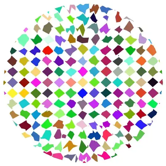
RegionPlot[Disk[], Mesh -> 20, 
 MeshFunctions -> {# + #2  RandomReal[{1, 1.2}] &, 
     # + #2 RandomReal[{-1.2, -1.}] &}, 
 MeshStyle -> {Directive[Thick, White], Directive[Thick, White]}, 
 PlotStyle -> None, 
 MeshShading -> Dynamic[{{RandomColor[], White}, {White, 
     RandomColor[]}}], BoundaryStyle -> None, Frame -> False, 
 ImageSize -> Large]

enter image description here

Block[{z = u + I v, pa = PadeApproximant[Exp[z], {z, 0, {5, 0}}]}, 
 RegionPlot[Abs[pa/Exp[z]] > 1, {u, -4, 4}, {v, -4, 4}, 
  ImageSize -> Large, PlotPoints -> 100, Mesh -> 70, 
  MeshFunctions -> {#1 + #2 &, #1 - #2 &},
  MeshShading -> {{White, Cyan}, {Orange, White}}, 
  MeshStyle -> {Directive[AbsoluteThickness[1], Blue], 
    Directive[AbsoluteThickness[1], Red]}, PlotStyle -> None, 
  BoundaryStyle -> None, Frame -> False]]

enter image description here

See also: This answer to a related Q/A

kglr
  • 394,356
  • 18
  • 477
  • 896
  • That is a really neat example, changing the value of the Mesh parameter will modify the spacing between lines, but how do you change MeshFunctions to obtain different angles? – Guillermo Oliver May 05 '20 at 10:18
  • @GuillermoOliver, I added an example showing how to get different angles. – kglr May 05 '20 at 10:20
  • In case I have to combine it with other Graphics, how should I do this? Using this RegionPlot approach results in an error message: GraphicsBox is not a Graphics primitive or directive. – Guillermo Oliver May 05 '20 at 10:26
  • 1
    @GuillermoOliver, you can use Show[RegionPlot[....], Graphics[....], PlotRange->All]. – kglr May 05 '20 at 10:29
  • 1
    Thank you for this answer. I guess the vectorization issue with HatchFilling will be addressed in the next version of Mathematica. – Guillermo Oliver May 05 '20 at 10:42