Edit 01:
The original question asked about a commensurate MoS$_2$ moire. It has since been updated to ask about only the coordinates of an MoS$_2$ monolayer. Considering the answer to the original question might be useful to other people, I'll leave this up. The answer to the updated question only can be found in the second code block.
Original answer
The commensurability of the moire cell is a property of the lattice vectors, not the motif. As such - you can use the following to compute the commensurate angles and commensurate moire cell for two twisted hexagonal lattices (with the same lattice constant):
hexagonalLattice[hexagonalLatticeConstant_] :=
 hexagonalLatticeConstant {{Sqrt[3]/2, 1/2}, {-(Sqrt[3]/2), 1/2}}
commensurateRotationAngle[{m_, n_}] :=
 With[{cos = (n^2 + 4 n m + m^2)/(2 (n^2 + n m + m^2))}, ArcCos[cos]]
commensurateCell[latticeVectors_, {m_,n_}] := {{n,-m}.latticeVectors, {m,n+m}.latticeVectors}
After that, it's a matter of decorating the moire cell with the appropriate honeycomb motif for each layer. Here is an example of a (6,7) commensurate moire cell for twisted bilayer MoS$_2$:
moS2Lattice = ArrayPad[hexagonalLattice[3.19], {{0, 1}, {0, 1}}, 0.];
moS2Lattice[[3, 3]] = 14.879;
distance["Mo-S"] = 1/10;
moS2BilayerMotif = {
   {1/3, 2/3, 1/4}, {2/3, 1/3, 1/4 + distance["Mo-S"]}, {2/3, 1/3,
    1/4 - distance["Mo-S"]},
   {2/3, 1/3, 3/4}, {1/3, 2/3, 3/4 + distance["Mo-S"]}, {1/3, 2/3,
    3/4 - distance["Mo-S"]}};
Note I define the full bilayer motif here, the first three coordinates refer to the bottom layer, while the last three to the top layer.
We can visualize this to make sure it looks correct for the untwisted case:
cols = Association[Map[ElementData[#, "AtomicSymbol"] -> ElementData[#, "IconColor"] &, {"Molybdenum", "Sulfur"}]];
moS2Colors = {Darker[cols["Mo"]], Darker[cols["S"]], Darker[cols["S"]], cols["Mo"], cols["S"], cols["S"]};
Graphics3D[
 Thread[{moS2Colors,
   Sphere /@ (Outer[Plus, moS2BilayerMotif,
       Tuples[{Range[-3, 3], Range[-3, 3], {0}}], 1] . moS2Lattice)}],
  ViewPoint -> {0, \[Infinity], 0}, Boxed -> False]

Now, we can make two large copies of an untwisted bottom layer and a twisted top layer, and then punch out the atoms inside our moire cell:
moireCellRM =
  RegionMember[
   Polygon[{{0, 0}, {1, 0}, {1, 1}, {0, 1}} .
     commensurateCell[moS2Lattice[[;; 2, ;; 2]], {6, 7}]]];
moS2Bottom =
  Table[Select[atom,
    moireCellRM[#[[;; 2]]] &], {atom, (Outer[Plus,
       Take[moS2BilayerMotif, 3],
       Tuples[{Range[-20, 20], Range[-20, 20], {0}}], 1] .
      moS2Lattice)}];
moS2Top =
  Table[Select[atom,
    moireCellRM[#[[;; 2]]] &], {atom, (Outer[Plus,
       Drop[moS2BilayerMotif, 3],
       Tuples[{Range[-20, 20], Range[-20, 20], {0}}], 1] .
      RotationTransform[commensurateRotationAngle[{6, 7}], {0, 0, 1}][
       moS2Lattice])}];
Let's visualize these to make sure it looks correct:
singleCell = {
   Thread[{Take[moS2Colors, 3], Sphere /@ moS2Bottom}],
   Thread[{Drop[moS2Colors, 3], Sphere /@ moS2Top}]};
twistedMoire =
 Graphics3D[singleCell, ViewPoint -> {0, 0, [Infinity]},
  Boxed -> False, ImageSize -> 350]

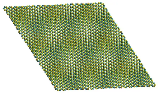
and finally tile the plane to make it even clearer:
twistedMoireLarge = Graphics3D[
   Table[
    GeometricTransformation[singleCell,
     TranslationTransform[{i, j, 1} .
       ArrayPad[
        commensurateCell[
         moS2Lattice[[;; 2, ;; 2]], {6, 7}], {{0, 1}, {0,
          1}}]]], {i, -1, 1}, {j, -1, 1}],
   ViewPoint -> {0, 0, \[Infinity]}, Boxed -> False,
   ImageSize -> 750] // Rasterize