3

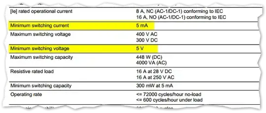
I want to use a Raspberry Pi to drive this relay. It is solid state, SP/ST, needs 12V for the coil and can switch up to 16A at 250V AC.

Now, I know that The RPi cannot switch natively anything above 3V and I have already found a circuit doing just that, switching a 12V relay from 5V logic.

My question is this. Is there a better way to do this? I would really like something a bit more "professional" because it will go in the electrical cabinet as part of a permanent installation. Ideally, I think, this should be electrically isolated from the RPi and also have some sort of protection, in the form of a fuse or something like that.

dlyk1988
  • 175
  • 1
  • 1
  • 6

4 Answers4

3

The Pi's gpios are 3V3 not 5V.

I couldn't make out from the datasheet the needed current to operate the relay contacts.

Assuming it is less than, say, 250 mA, I'd use a ULN2003A or similar to operate the contacts. It has in-built fly-back protection and can be operated by the Pi's gpios.

I'm a software type though. There are probably better sites for this sort of question.

joan
  • 71,014
  • 5
  • 73
  • 106
3

I had that same problem for my Pool Timer. Schematic, parts and reasoning are here: http://upon2020.com/blog/2012/12/my-raspberry-pi-pool-timer-electronic-assembly/

It's been working in production for almost 2 years now.

Johannes Ernst
  • 233
  • 1
  • 7
2

Add a transistor drive step to your relay which in turn switches the high voltage circuit. (but yes you will also need a 12 Volt power supply to drive the relay, a volt relay could be better as you will have that voltage available)

http://apps.usd.edu/coglab/psyc770/transistors101.html

Simson
  • 131
  • 4
1

The specification clearly "but mixed in with allot of other things"

enter image description here

5ma (300mW) @ 5V 12V @ 33mA needs to be applied to drive the relay. The GPIO pins them selves wont be able to do it because they are 3.3v. You can solve this by using a logic level shifter like MAX 3370 or as seen on Sparkies

Piotr Kula
  • 17,307
  • 6
  • 65
  • 104
  • Looking at it again it seems to need 33mA at 12V to operate the relay coils (360R coils). This gives 400mW against the quoted average of 450mW. – joan Nov 07 '14 at 12:41
  • Where do you see that? Damn that must be the worst data sheet ever. – Piotr Kula Nov 07 '14 at 13:18
  • I was looking at "Control circuit voltage 12 V DC" and "Average coil resistance 360 Ohm (DC) at 20 °C +/- 10 %" and "Average coil consumption 0.45 W DC". Look at the DHT22 for a bad data sheet contender! – joan Nov 07 '14 at 13:24
  • LOL. That is pretty bad :) OK I updated it. Thanks – Piotr Kula Nov 07 '14 at 13:28