Your design should consist of 3 stages.
- Software for the LCD screen and trigger a GPIO ON(HIGH) and OFF(LOW)
- Low voltage relay control system 3.3v (GPIO)
- High voltage control system (12 volt)
Low and high voltage here are relative to the GPIO of the Pi. 3.3v is low voltage and 12volt is high voltage, since they are not compatible.
Software
You can use any software you like. The most popular for the Pi is Python, because it has a rich library for GPIO, Touchscreens, GUI, Webservers, etc.
Since you not sure about the software you should concentrate on this before getting to the wiring part, which will be easier for you any way.
Low voltage (White Area)
Very simple schematics are involved here. Basically requiring you to wire the GPIO outputs to the 12 volt system in a safe way, using transistors, to turn on the Relays. This is also low power (amps). You must not drive high loads with the GPIO, like relays directly. It will cause damage to the Pi. Treat the Pi like a fragile brain (ARM), sending signals to the muscles (Transistors/Relays)
High Voltage (Yellow Area)
This will be your main 12volt system used in your car. Make sure to use good, thick enough copper wire that will be powering the lights, from the start to the end. A good tip is to use slightly bigger negative wire but connect it as close as possible to the chassis (which should be all negative)
The schematics
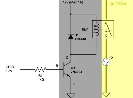
Low/High Voltage (Grey Area)
This is where your brain (MCU) and muscle (Transistor/Relay) come into a critical compromise. You turn on the relay by driving a transistor, like 2N3904 or 2N2222 on the BASE This ensures that low voltage and low amperage are used to switch a high loads (Amps) .
Here you can use normal core wire since you are only driving the relay and not the lights yet. You take 12v+ from battery (1A/2A FUSED! But one is enough to drive several relays) and connect it to the relay/s, the output form the relay goes to the COLLECTOR of the transistor, and the EMITTER goes to GND - Which ground? Well in this case the cars ground is fine, since you are powering the Pi with a power adapter connected to the same ground essentially. What you want to avoid is a floating ground. Say powering the Pi separately, from a separate battery, that is another problem.
The diode D1 is across the INPUT and the OUTPUT of the Relay. This is essentail to stop fly back current produced by the magnetic coil in the relay. The symbol of the arrow is important, as you know.
The yellow zone is your high voltage high power, with cables suitable for the lights you are driving. 5A / 10A / 15A. Also, all fused (separately) as close to the battery as possible and GND as close to the chassis as possible (or common GND on cars with lots of electronics)
You repeat this as many times as you need. You may want to put all the elements on a bread board, the transistors and relay output. Basically, when you drive the GPIO HIGH, the transistor will allow the 12volts to "flow" to GND, turning on the relay, which turns on your lights.
Even with 5volt relays, you need this, because the GPIO is not supposed to do heavy lifting of any sort.