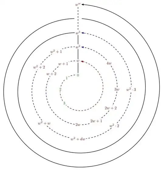
I found it an interesting challenge, since it is about placing terms in something similar to a spiral, searching I found this very detailed code from Guilherme Zanotelli to draw parametric spirals, and then I adapted it to obtain a similar result, I have used some nesting to place the nodes.
RESULT:
MWE:
\documentclass[tikz,border=0.5cm]{standalone}
%this code is from Guilherme Zanotelli  in a "short" explanation in https://tex.stackexchange.com/a/333824/154390 [start]
\newcommand\bonusspiral{} % just for safety
% \bonusspiraldraw options(start angle:end angle)(start radius:final radius)[revolutions]
\def\bonusspiral#1(#3:#4)(#5:#6)[#7]{
    \pgfmathsetmacro{\domain}{#4+#7360}
    \pgfmathsetmacro{\growth}{180(#6-#5)/(pi(\domain-#3))}
    \draw [#1,
    shift={(#2)},
    domain=#3pi/180:\domainpi/180,
    variable=\t,
    smooth,
    samples=int(\domain/5)] plot ({\t r}: {#5+\growth\t-\growth#3pi/180});
}
%this code is from Guilherme Zanotelli  in a "short" explanation in https://tex.stackexchange.com/a/333824/154390 [end]
%Modification to put a node in specific point of the function
%\NodeOnSpiraldraw options(start angle:end angle)(start radius:final radius)[revolutions]{node_position_in_degrees}{node content}
\def\NodeOnSpiral#1(#3:#4)(#5:#6)[#7]#8#9{
    \pgfmathsetmacro{\dom}{#4+#7360}
    \pgfmathsetmacro{\grow}{180(#6-#5)/(pi(\dom-#3))}
    \path [
        shift={(#2)},
        domain=#3pi/180:\dompi/180,
        variable=\j,
        smooth,
        samples=int(\dom/5),
        samples at=#8pi/180
    ]
        plot ({\j r}: {#5+\grow\j-\grow#3*pi/180})
        node[
            #1,
            rectangle,
            fill=white,
            inner sep=2pt,
            scale=0.8
        ]{#9};
}
\begin{document}
    \begin{tikzpicture}[>=latex]
    %Start drawing the thing.
    % First spiral is used as workspace a spiral that starst from 90 at radious 1 and ends at 90 at radious 6.
    \bonusspiralblack!10,dotted, thick(90:90)(1:6)[5]
% Draw a line from (90:1) to (90:6)
\draw[thick] (90:1) -- (90:4);
\draw[thick,dashed] (90:4) -- (90:6);

% Draw the first spiral arrow in one revolution from 90:1 to 85:2. no to 90:2 to not put the arrow interrupting the node
\bonusspiral[red!50!black,dashed, thick,->](0,0)(90:85)(1:2)[1]
% Put the nodes in their corresponding angle position in the spiral.
\foreach  \degpos/\nodetext in {
    90/0,
    135/1,
    180/2,
    225/3%
}{\NodeOnSpiral[green!50!black](0,0)(90:90)(1:3)[2]{\degpos}{$\nodetext$}}

% Draw the second spiral arrow in one revolution from 90:2 to 85:3.
\bonusspiral[blue!50!black,dashed, thick,->](0,0)(90:86)(2:3)[1]
% same thing in the corresponding spiral and revolution angle.
\foreach  \degpos/\nodetext in {
    450/w,
    480/w+1,
    510/w+2,
    630/2w,
    660/2w+1,
    690/2w+2,
    720/3w,
    760/4w%
}{\NodeOnSpiral[red!50!black](0,0)(90:90)(1:3)[2]{\degpos}{$\nodetext$}}

% Draw the third spiral arrow in one revolution from 90:3 to 85:4.
\bonusspiral[blue!50!black,dashed, thick,->](0,0)(90:87)(3:4)[1]
% same thing in the corresponding spiral and revolution angle.
\foreach  \degpos/\nodetext in {
    810/w^2,
    840/w^2+1,
    870/w^2+2,
    945/w^2+w,
    990/w^2+dw,
    1035/w^2\cdot2,
    1080/w^2\cdot3%
}{\NodeOnSpiral[red!50!black](0,0)(90:90)(1:3)[2]{\degpos}{$\nodetext$}}

% Draw the last spirals arrow in two revolutions from 95:4 to 88:6.
\bonusspiral[black, thick](0,0)(93:87)(4:5)[1]
\bonusspiral[black, thick,->](0,0)(93:88)(5:6)[1]
% same thing in the corresponding spiral and revolution angle.
\foreach  \degpos/\nodetext in {
    1170/w^3,
    1890/w^w%
}{\NodeOnSpiral[red!50!black](0,0)(90:90)(1:3)[2]{\degpos}{$\nodetext$}}


\end{tikzpicture}

\end{document}


(r:phi)-- note the semi-colon -- where r is the distance to the center, and phi the polar angle (by default in degrees). In the present case, you woukd use an r defined as a linear fiction of phi, in order to produce the spiraling shape. And the size issue could be solved by using globally a smaller font like e.g.,\footnotesize, or increase the canvas size by providing[x=15mm,y=15mm]or similar as a option for the tikz picture. – Jhor Mar 07 '22 at 00:39