4

This might be a trivial question and I saw similar questions but for some reason, I did not manage to resolve it.

Consider this slide

\documentclass{beamer}
\usefonttheme[onlymath]{serif}
\setbeamercovered{transparent}
\mode<presentation> {
\usetheme{Boadilla}
}
\begin{document}
\begin{frame}
\begin{align*}
y = ax + b
\end{align*}
\end{frame}
\end{document}

We would like to first see the expression and then highlight ax by adding a color-filled square on it.

How can we do it? There's a very close but complicated question and answer here but I wasn't able to use it.

4 Answers4

6

You can use tikz for that

\documentclass{beamer}
\usepackage{tikz}
\usefonttheme[onlymath]{serif}
\setbeamercovered{transparent}
\mode<presentation> {
\usetheme{Boadilla}
}
\begin{document}
\begin{frame}
\begin{align*}
y = 
\tikz\node[draw=red, inner sep=6pt, circle, overlay, shift={(6pt,2pt)}]{};
ax + b
\end{align*}
\end{frame}
\end{document}

enter image description here

By changing inner sep, you can increase or decrease the diameter. In order to change the shape, replace circle with something else, rectangle for instance.

enter image description here

List of shapes can be found in the manual 71.2 Predefined Shapes

antshar
  • 4,238
  • 9
  • 30
  • Thank you. I understood pretty much everything except for shift={(6pt,2pt)}. What is that for? –  Jun 01 '22 at 12:57
  • @VultraUiolet the node also has overlay option. It's required to draw the shape on top, without interfering the text (otherwise, node becomes part of the text, you can experiment by removing this option). So with overlay you'd want to move the shape so that ax becomes inside of it. (6pt, 2pt) means that the node is being shifted by 6pt to the right and 2pt to the top. – antshar Jun 01 '22 at 13:06
5

Edit: Ups, I forgot on other shapes ... Added now:

With tikzmark library:

\documentclass{beamer}
\mode<presentation> 
{
\usetheme{Boadilla}
}
\usepackage{tikz}
\usetikzlibrary{shapes,
                tikzmark}
\tikzset{every tikzmarknode/.style={%
        draw=red, semithick, inner sep=2pt}
        }

\begin{document} \begin{frame} With circle [ y = \tikzmarknode[circle]{n1}{ax} + b\ , ] ellipse [ y = \tikzmarknode[ellipse]{n1}{ax} + b\ , ] rectangle shape: [ y = \tikzmarknode[rectangle]{n1}{ax} + b\ , ] and rectange wit rounded corners: [ y = \tikzmarknode[rectangle, rounded corners]{n1}{ax} + b ] \end{frame} \end{document}

enter image description here

Addendum: For uncovering highlighted elements in equation can be done by use of \alt command (from beamer) as suggested @Unknown in his comments, for uncovering of sequence of equations can be used \onslide commands as is done in the following MWE

\documentclass{beamer}
\mode<presentation>
{
\usetheme{Boadilla}
}
\usepackage{tikz}
\usetikzlibrary{shapes,
                tikzmark}
\tikzset{every tikzmarknode/.style={%
        draw=red, semithick, inner sep=2pt},
        ALT/.style = {opacity=0,text opacity=1},
        }
\newcommand\mystrut[1]{\rule{0pt}{#1}}

\begin{document}

\begin{frame} With circle [ y = \alt<2>{\tikzmarknode[circle]{n1}{ax}} {\tikzmarknode[circle, ALT]{n1}{ax}} + b, , ] \onslide<3->{ some text followed by next equation which for highlight use ellipse [ y = \mystrut{2.7ex} \alt<4>{ax^2 + \tikzmarknode[ellipse]{n1}{bx}} {ax^2 + \tikzmarknode[ellipse, ALT]{n1}{ax}} + c, , ] } \onslide<5->{ and test with rectangle shape: [ y = \sum_{a=1}^n \alt<6>{\tikzmarknode[rectangle]{n1}{ax}} {\tikzmarknode[rectangle, draw=white]{n1}{ax}} + b, , ] } \end{frame} \end{document}

enter image description here enter image description here enter image description here

A case when sequentially are uncovered terms and in the next equation:

\documentclass{beamer}
\mode<presentation>
{
\usetheme{Boadilla}
}
\usepackage{tikz}
\usetikzlibrary{shapes,
                tikzmark}
\tikzset{every tikzmarknode/.style={%
        draw=red, semithick, inner sep=2pt},
        ALT/.style = {opacity=0,text opacity=1},
        }
\newcommand\mystrut[1]{\rule{0pt}{#1}}

\begin{document} \begin{frame} \begin{align} y & = \alt<2>{\tikzmarknode[circle]{n1}{a^2x}} {\tikzmarknode[circle, ALT]{n1}{a^2x}} + bx + c, , \ \onslide<3->{ & = \mystrut{2.7ex} \alt<4>{ax^2 + \tikzmarknode[ellipse]{n2}{bx}} {ax^2 + \tikzmarknode[ellipse, ALT]{n2}{ax}} + c, , \ } \onslide<5->{ & = \mystrut{2.7ex} \alt<6>{ax^2 + bx + \tikzmarknode[rectangle]{n3}{c}} {ax^2 + bx + \tikzmarknode[rectangle, ALT]{n3}{c}}, , }
\end{align
} \end{frame} \end{document}

enter image description here

Note: for correct positioning of frame contents MWE had to be compiled at least twice.

Edit: Thank to @Andrew Stacey (see his comment below) the MWE now works as expected. As he suggested, in above codes now are changed \alt<4->{...} to \alt<4>{...} (and the same at \alt<6 ...).

Zarko
  • 296,517
  • Thank you. I'm not sure if I implemented it well but I don't get the sequential appearance. I mean the ax and the circle are there in one slide. We would like to first see the expression, then highlight it with a circle. –  Jun 01 '22 at 15:13
  • @VultraUiolet Here is one possibility to add this effect: \alt<2>{\tikzmarknode[circle]{n1}{ax}{\tikzmarknode[circle,draw=white]{n1}{ax}}. If we do not want the highlighting, we draw the shape white (= background color). You will achieve the same effect if you use two times \only. – Unknown Jun 02 '22 at 19:25
  • @VultraUiolet Another possibility: \alt<2>{\tikzmarknode[circle]{n1}{ax}{\tikzmarknode[circle, opacity=0,text opacity=1]{n1}{ax}} – Unknown Jun 02 '22 at 19:31
  • You ca mske styles overlay-aware, see https://tex.stackexchange.com/a/6155/86 and also the aobs-beamer package. – Andrew Stacey Jun 03 '22 at 09:05
  • @AndrewStacey, thank you for info. I will check this late evening (after finishing my job in my workshop :-) ) – Zarko Jun 03 '22 at 09:19
  • Description of the \alt (= alternative) command from the beamer manual: \alt<2>{On Slide 2}{Not on slide 2.}. I suggest to use the \temporal command: \temporal<3-4>{Shown on 1, 2}{Shown on 3, 4}{Shown 5, 6, 7, ...} or simply \alt<4> instead of \alt<4-> inside \onslide. – Unknown Jun 03 '22 at 17:48
  • @Unknown, thank you very much for your comments. I'm aware for all this possibilities, but today unfortunately so far I haven't spare time to write new addendums to answer. So, please be so kind and write own answer with your suggestions. I will upvote it ;-) – Zarko Jun 03 '22 at 17:55
  • The reason the highlighting from the second line persists is because you have the specification <4-> on the \alt in that second equation. Change it to <4> and the highlighting will only be on a single slide. Also, I note that you're using opacity to get round the jumping issue when lines are drawn or not drawn - neat idea! – Andrew Stacey Jun 04 '22 at 08:54
  • @AndrewStacey Thanks for repeating my suggestion to fix the highlight error, i. e. my last comment. :-) Probably the reference to the highlight error was not clear. – Unknown Jun 04 '22 at 18:50
  • @Unknown my apologies - I did not read your comment beyond the suggestion to use \temporal so missed your correction of the \alt command (I have a bad habit of often only skim reading comments). – Andrew Stacey Jun 04 '22 at 19:56
  • @zarko may I suggest editing the attribution of the correction to the \alt command? – Andrew Stacey Jun 04 '22 at 19:58
  • @AndrewStacey, of course. – Zarko Jun 04 '22 at 23:58
1

I just want to highlight something with regard to spacing. This should be considered an extended comment on the solutions above.

To avoid terms jumping around when switching frames then it is necessary to think about how things affect the spacing, in particular with regard to the line width of any highlighting path.

To understand this, it is worth digging deeper into what the inner and outer seps are, and how they interact with the line width. The boundary of a node is considered to be a rectangle that is inner sep out from the natural boundary of the node's contents (both inner sep and outer sep can be set to different values horizontally and vertically but that's not important so I'll ignore it here). If the node is drawn, then that is the path that is used (there are adjustments for other shapes, but they all start from the inner rectangle so again, I'll ignore that here). However, paths are drawn with thickness and this thickness is equally spaced either side of the "perfect" path, so a drawn node has an apparent size that is slightly bigger - by half the line width - of its actual size. The outer sep is designed to deal with this as it is added to the parts of a node's setup that might be relevant outside the node (ie anchors). By default, the outer sep is set to half the current line width. So if the line width is changed for the drawing command then the node's size will change between frames. There is a further complication in that when TikZ tells TeX how big the drawing is then it uses a different calculation depending on whether the node was drawn or not. If not drawn then it uses the exact path but if drawn then it enlarges it by half the line width. So although the outer sep may be set correctly, it doesn't have the right effect if the node is not drawn. It turns out, though, that TikZ is a bit clever and so will set the outer sep to 0pt (rather than half the line width) if the boundary is not drawn. This can be used to correct the inner sep so that the node is always the right size regardless of whether it is drawn or not.

The key question is, therefore: should the equation look like it would if written without any adornment or should space be reserved for the highlighting?

If the adornment is an overlay, then use tikzmarknode with no style and add the highlighting afterwards. The fit library can be really useful here.

If the adornment is inline, then add the styling options to the tikzmarknode but make sure that all options that affect its size are always present (in particular, line width). So only change the draw (or fill) command between frames.

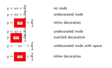
The following is an example showing various combinations together with what it looks like with the jumping effect.

% Flush left all equations to make width changes more evident
\PassOptionsToPackage{fleqn}{amsmath}
\documentclass{beamer}
%\url{https://tex.stackexchange.com/q/646378/86}
\usefonttheme[onlymath]{serif}

\usepackage{tikz}

% tikzmark for positioning, % fit for adding adornments to existing nodes \usetikzlibrary{ tikzmark, fit }

%\setbeamercovered{transparent} \mode<presentation> { \usetheme{Boadilla} }

\tikzset{ % Beamer-aware styles only/.code args={<#1>#2}{% \only<#1>{\pgfkeysalso{#2}} }, temporal/.code args={<#1>#2#3#4}{% \temporal<#1>{\pgfkeysalso{#2}}{\pgfkeysalso{#3}}{\pgfkeysalso{#4}} % }, alt/.code args={<#1>#2#3}{% \alt<#1>{\pgfkeysalso{#2}}{\pgfkeysalso{#3}} % }, % Shortcut for the style surround/.style={ draw=#1, rectangle, line width=3mm, % If draw is none, then TikZ sets the outer x/y seps to 0pt % meaning that this increases the inner x/y seps by half the line width % If draw is not none then the default outer seps are half the % line width so the inner seps are 2mm inner xsep=2mm + .5\pgflinewidth - \pgfkeysvalueof{/pgf/outer xsep}, inner ysep=2mm + .5\pgflinewidth - \pgfkeysvalueof{/pgf/outer ysep}, outer sep=auto }, highlight/.style={ only=<5>{surround=none}, % braces needed as there's a comma in the overlay specification only={<2,6>{surround=red}} }, }

% Alignment marker to make the changes obvious \NewDocumentCommand\Marker{ O{.3333} }{% \tikz[overlay] \draw[line width=.5pt] (0,.5ex) +(0,#1) -- +(0,-#1) +(-.1,#1) -- +(.1,#1) +(-.1,-#1) -- +(.1,-#1);% }

\begin{document} \begin{frame}<1-6>[t] % top-aligned to show vertical jumping \begin{align} y & = ax + b \Marker \ y &= \tikzmarknode[highlight]{ax-mark}{ax} + b \Marker \ \end{align}

\only<1>{Slide 1: no decoration, equations are perfectly aligned} \only<2>{Slide 2: decoration on the tikzmarknode, adds space so that decoration does not overlap other elements} \only<3>{Slide 3: as slide 1} \only<4>{Slide 4: decoration added after, equations are perfectly aligned, decoration may overlap other elements} \only<5>{Slide 5: no decoration, but outer sep adjusted so that space is reserved for decoration} \only<6>{Slide 6: as slide 2, showing no jump from slide 5}

% Overlaid highlighting visible on slide 4 \tikz[overlay, remember picture] \node[fit=(ax-mark),only=<4>{surround=red}] {}; \end{frame} \end{document}

Here's a flattened version of the above:

Highlighting terms in an equation, showing the various spacing options

Note: I've assumed that you're wanting to drawn round the term you wish to highlight which is consistent with what the others have gone with. If you wish to highlight by filling then a lot of the issues with spacing adjustments go away as a filled path has no width. But then that brings additional considerations with whether the filled region should be behind the text or in front of it. If that is something you want to consider, leave a comment clarifying.

Andrew Stacey
  • 153,724
  • 43
  • 389
  • 751
  • Great description, thanks. If you repeat the highlighting effect using the version based on undecorated node with space, the viewers know at the latest after the 2nd time that the expression with extra space is also framed again in color. So the framing has then no real highlight effect anymore. – Unknown Jun 03 '22 at 18:15
  • 1
    @Unknown Fair point, but I've used very thick lines for effect, it would be more normal to have ultra thick or thinner, in which case someone at the back of the hall may not be able to distinguish between with and without spacing. There's also the suspense as to when the term will be highlighted - just knowing that it will be highlighted doesn't tell you when it's going to happen (got to provide something to keep the students awake!). – Andrew Stacey Jun 04 '22 at 08:43
1

You can use the hf-tikz package:

\documentclass{beamer}
\usefonttheme[onlymath]{serif}
\setbeamercovered{transparent}
\mode<presentation> {
\usetheme{Boadilla}
}

\usepackage[beamer]{hf-tikz}

\begin{document} \begin{frame} \begin{align} y = \tikzmarkin<2->{a}ax\tikzmarkend{a} + b \end{align} \end{frame} \end{document}

enter image description here