@Zarko's answer is the correct way to do it. I would suggest using the midtap anchor and judicious use of mirror to make it general for other L-shapes.
Notice that the use of mirror is a bit of an "adjust it" thing, because it depends on the shape and on how many "loops" you have in the inductance...
\documentclass[margin=2.718mm]{standalone}
\usepackage[siunitx, RPvoltages]{circuitikz}
\usetikzlibrary[arrows.meta]
\begin{document}
\begin{circuitikz}[]
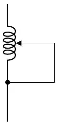
\draw (0,0) to [short,-*] ++ (0,1) coordinate (a)
to [L, mirror, name=L] ++ (0,2);
\draw[Stealth-] (L.midtap) -- ++ (1,0) |- (a);
\begin{scope}[american, xshift=3cm]
\draw (0,0) to [short,-*] ++ (0,1) coordinate (a)
to [L, name=L] ++ (0,2);
\draw[Stealth-] (L.midtap) -- ++ (1,0) |- (a);
\end{scope}
\begin{scope}[american, xshift=6cm,
circuitikz/inductors/coils=5]
\draw (0,0) to [short,-*] ++ (0,1) coordinate (a)
to [L, mirror, name=L] ++ (0,2);
\draw[Stealth-] (L.midtap) -- ++ (1,0) |- (a);
\end{scope}
\begin{scope}[european, xshift=9cm]
\draw (0,0) to [short,-*] ++ (0,1) coordinate (a)
to [L, mirror, name=L] ++ (0,2);
\draw[Stealth-] (L.midtap) -- ++ (1,0) |- (a);
\end{scope}
\end{circuitikz}
\end{document}

If you want the same "fake" arrow of the rest of circuitikz(*), you can:
\documentclass[margin=2.718mm]{standalone}
\usepackage[siunitx, RPvoltages]{circuitikz}
\usetikzlibrary[arrows.meta]
\begin{document}
\begin{circuitikz}[]
\draw (0,0) to [short,-*]   ++ (0,1)  coordinate (a)
            to [L, mirror,  name=L]  ++ (0,2);
            \draw[]   (L.midtap) node[inputarrow, xscale=-1]{}
            --  ++ (1,0)   |-  (a);
\end{circuitikz}
\end{document}
(*) For a bit more details about arrows in circuitikz, see https://tex.stackexchange.com/a/549354/38080


