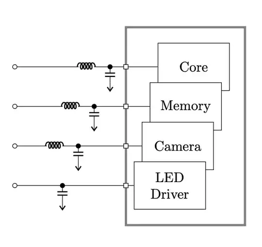
\documentclass[tikz, border=1cm]{standalone}
\usepackage[american, siunitx]{circuitikz}
\begin{document}
\begin{tikzpicture}[transform shape, scale=1,]
\ctikzset{
inductors/scale=0.5,
capacitors/scale=0.3,
power supplies/scale=0.5,
}
\draw[ultra thick, gray] (2.8,4) rectangle +(3,-5);

\draw[yshift=3cm] (0,0) to[short, o-] ++(1.6,0) to[cute inductor] ++(0.4,0) to[short,-*] ++(0.4,0) coordinate(C1) to[short] (2.8,0) node[osquarepole]{} to[short] ++(0.8,0) node[draw, fill=white, minimum height=1.2cm, minimum width=1.8cm, right]{Core};
\draw (C1) to[C] ++(0,-0.4) node[vee]{};

\draw[yshift=2cm] (0,0) to[short, o-] ++(1.2,0) to[cute inductor] ++(0.4,0) to[short,-*] ++(0.4,0) coordinate(C2) to[short] (2.8,0) node[osquarepole]{} to[short] ++(0.6,0) node[draw, fill=white, minimum height=1.2cm, minimum width=1.8cm, right]{Memory};
\draw (C2) to[C] ++(0,-0.4) node[vee]{};

\draw[yshift=1cm] (0,0) to[short, o-] ++(0.8,0) to[cute inductor] ++(0.4,0) to[short,-*] ++(0.4,0) coordinate(C3) to[short] (2.8,0) node[osquarepole]{} to[short] ++(0.4,0) node[draw, fill=white, minimum height=1.2cm, minimum width=1.8cm, right]{Camera};
\draw (C3) to[C] ++(0,-0.4) node[vee]{};

\draw[yshift=0cm] (0,0) to[short, o-] ++(0.8,0) to[short,-*] ++(0.4,0) coordinate(C4) to[short] (2.8,0) node[osquarepole]{} to[short] ++(0.2,0) node[draw, fill=white, minimum height=1.2cm, minimum width=1.8cm, right, align=center]{LED\\Driver};
\draw (C4) to[C] ++(0,-0.4) node[vee]{};

\end{tikzpicture}
\end{document}
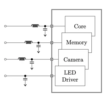
Edit: With custom cross pins
\documentclass[tikz, border=1cm]{standalone}
\usepackage[american, siunitx]{circuitikz}
\begin{document}
\begin{tikzpicture}
\tikzset{
cross/.style={
draw, fill=white, inner sep=2pt,
path picture={\draw
(path picture bounding box.south east) --
(path picture bounding box.north west)
(path picture bounding box.south west) --
(path picture bounding box.north east);
}}}
\ctikzset{
inductors/scale=0.5,
capacitors/scale=0.3,
power supplies/scale=0.5,
}
\draw[ultra thick, gray] (2.8,4) rectangle +(3,-5);
\draw[yshift=3cm] (0,0) to[short, o-] ++(1.6,0) to[cute inductor] ++(0.4,0) to[short,-*] ++(0.4,0) coordinate(C1) to[short] (2.8,0) node[cross]{} to[short] ++(0.8,0) node[draw, fill=white, minimum height=1.2cm, minimum width=1.8cm, right]{Core};
\draw (C1) to[C] ++(0,-0.4) node[vee]{};
\draw[yshift=2cm] (0,0) to[short, o-] ++(1.2,0) to[cute inductor] ++(0.4,0) to[short,-*] ++(0.4,0) coordinate(C2) to[short] (2.8,0) node[cross]{} to[short] ++(0.6,0) node[draw, fill=white, minimum height=1.2cm, minimum width=1.8cm, right]{Memory};
\draw (C2) to[C] ++(0,-0.4) node[vee]{};
\draw[yshift=1cm] (0,0) to[short, o-] ++(0.8,0) to[cute inductor] ++(0.4,0) to[short,-*] ++(0.4,0) coordinate(C3) to[short] (2.8,0) node[cross]{} to[short] ++(0.4,0) node[draw, fill=white, minimum height=1.2cm, minimum width=1.8cm, right]{Camera};
\draw (C3) to[C] ++(0,-0.4) node[vee]{};
\draw[yshift=0cm] (0,0) to[short, o-] ++(0.8,0) to[short,-*] ++(0.4,0) coordinate(C4) to[short] (2.8,0) node[cross]{} to[short] ++(0.2,0) node[draw, fill=white, minimum height=1.2cm, minimum width=1.8cm, right, align=center]{LED\Driver};
\draw (C4) to[C] ++(0,-0.4) node[vee]{};
\end{tikzpicture}
\end{document}


\normalsize,\small, ... andthin,thick, ... – hpekristiansen Dec 10 '22 at 12:39node[osquarepole, nodes width = 10pt]{}isn't correct and I don't see example in the manual. – internet Dec 10 '22 at 17:22node[osquarepole, scale=2]{}– hpekristiansen Dec 10 '22 at 17:32power supplies/scale=-0.5works at all is a (fortunate) coincidence. Better usepower supplies/scale=0.5and use aveenode... – Rmano Dec 10 '22 at 18:37