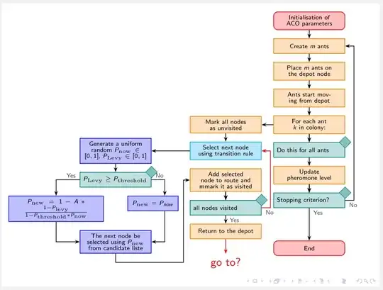
For fun and joy, but someone may liked ...
- new shapes for nodes (shape for decision node is designed by @Qrrbrbirlbel)
- added colors to nodes,
- use relative positioning
- for orthogonal arrow is used
ext.paths.ortho, library
- main branch is in chain
- no scaling
- text area in frame is widened by use
adjustwidth of changepage package
\documentclass{beamer}
\usepackage{tikz}
\usetikzlibrary{arrows.meta,
                chains,
                ext.paths.ortho,  % -|- and |-| path operations
                positioning,
                shapes}
\usepackage{changepage}
\begin{document}
\begin{frame}[fragile]
    \begin{adjustwidth}{-2em}{-1em}
    \centering
\begin{tikzpicture}[auto,
   node distance = 2.8mm and 4mm,
     start chain = going below,
      arr/.style = {semithick,-{Stealth[scale=0.8]}},
     base/.style = {draw=#1, semithick, fill=#1!25,
                    text width=22mm, minimum height=5mm, align=center,
                    inner sep=3pt,
                    font=\tiny\linespread{0.84}\selectfont,
                    on chain
                    },
       be/.style = {% BeginEnd
                    base=red, text width=#1, rounded corners},
     be/.default = 22mm,
       if/.style = {% decision node: https://tex.stackexchange.com/questions/661461
                    base=teal, align=left,
                    label={[D=teal]north east:}},
            D/.style   = {diamond, draw=#1, fill=#1!50, inner sep=1mm, anchor=center},
            lbl/.style = {inner sep=2pt, font=\tiny, text=black!75},
       ra/.style = {label={[lbl, anchor=south west]east:#1}},       % right above
       rb/.style = {label={[lbl, anchor=north west]east:#1}},       % right bbelo
       la/.style = {label={[lbl, anchor=north east]west:#1}},       % lrft above
       lb/.style = {label={[lbl, anchor=south east]west:#1}},       % left below
       bl/.style = {label={[lbl, anchor=north west]south:#1}},      % below lrfz
       br/.style = {label={[lbl, anchor=north west]south:#1}},      % below right
       pc/.style = {% ProCess
                    base=#1},
     pc/.default = orange,
       px/.style args = {#1/#2}{% ProcessExtend
                    base=#1, text width=#2},
%
off chain/.code={\def\tikz@lib@on@chain{}}          % <== defined interruption of chain
                    ]
%%  branche principale, les nœuds sont en chaîne
    \begin{scope}[nodes={join=by arr}]
\node[be]   (A) {Initialisation of ACO parameters};
\node[pc]   (B) {Create $m$ ants};
\node[pc]   (C) {Place $m$ ants on the depot node};
\node[pc]   (D) {Ants start moving from depot};
\node[pc]   (E) {For each ant $k$ in colony:};
%
\node[if,
      br=Yes?]   (F) {Do this for all ants};
%
\node[pc]   (G) {Update pheromone level};
%
\node[if,
      br=Yes,
      rb=No]   (H) {Stopping criterion?};
%
\node[be=11mm, below=11mm of H]  (End)   {End};
    \end{scope}
%% près de la branche gauche
\node[off chain, pc,
      left=of E]    (I) {Mark all nodes as unvisited};
\node[pc=cyan]      (J) {Select next node using transition rule};
\node[pc]           (K) {Add selected node to route and mmark it as visited};
      \begin{scope}[nodes={join=by arr}]
%
\node[if,
      rb=No,
      br=Yes]       (L) {all nodes visited};
%
\node[pc]           (M) {Return to the depot};
    \end{scope}
 %% branche extrême gauche
      \begin{scope}[nodes={off chain}]
\node[pc=blue,
      left=0mm and 13mm of J]

                    (N) {Generate a uniform random $P_{\mathrm{now}}\in[0,1]$, $P_{\mathrm{Levy}}\in[0,1]$};
%
\node[if=blue,
      la=Yes,
      rb=No,
      below=of N]   (O) {$P_{\mathrm{Levy}}\geq P_{\mathrm{threshold}}$};
%
\node[px=blue/30mm,
      below  left=of O.south]

                    (P) {$P_{\mathrm{new}}=
                                       1-A \ast \frac{1-P_{\mathrm{levy}}}{1-P_{\mathrm{threshold}}\ast P_{\mathrm{now}}}$};
 \node[px=blue/15mm,
      below right=of O.south]

                    (Q) {$P_{\mathrm{new}}=P_{now}$};
\node[pc=blue,
      below=of P.south -| O]

                    (R) {The next node be selected using $P_{\mathrm{new}}$ from candidate liste};
    \end{scope}
%% flèches, non incluses dans la macro de "join"
 \foreach \m/\n in {I/J, J/N, N/O}
    \draw[arr] (\m) -- (\n);
\draw[arr] (O) -| (P);
\draw[arr] (O) -| ([xshift=4mm] Q.north);
\draw[arr] (P) |- (R);
\draw[arr] ([xshift=4mm] Q.south) |- (R);
\draw[arr] (R.south) -- ++ (0,-0.5) -|- [distance=23mm] (K);
\draw[arr] (L.east) -|- [distance=-3mm] (J);
\draw[arr] (H.east) -|- [distance=-5mm]  (B);
\draw[arr, red] (M.south) -- ++ (0,-0.5) node[below] {go to?};
\end{tikzpicture}
    \end{adjustwidth}
\end{frame}
\end{document}
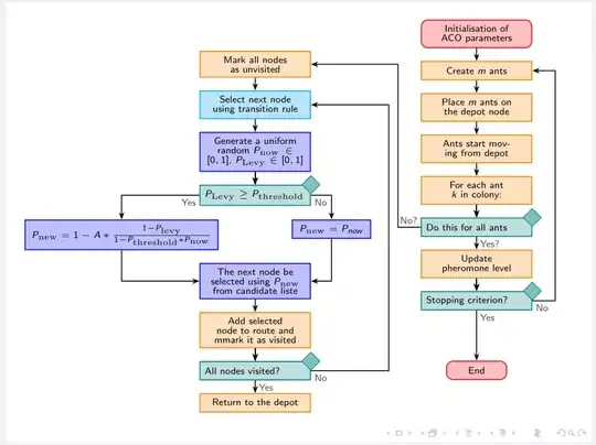
Addendum:
I estimate that more clear flowchart can be obtained, if both left branches are merged in one with beginning near top of main branch.
With such organized flowchart is more evident, where should interconnections arrows. However, I'm not sure, if they are really there as shown below.
\documentclass{beamer}
\usepackage{tikz}
\usetikzlibrary{arrows.meta,
                calc, chains,
                ext.paths.ortho,  % -|- and |-| path operations
                positioning,
                shapes}
\usepackage{changepage}
\begin{document}
\begin{frame}[fragile]
    \begin{adjustwidth}{-2em}{-1em}
    \centering
\begin{tikzpicture}[auto,
   node distance = 2.8mm and 24mm,
     start chain = going below,
      arr/.style = {semithick,-{Stealth[scale=0.8]}},
     base/.style = {draw=#1, semithick, fill=#1!25,
                    text width=22mm, minimum height=4mm, align=center,
                    inner sep=3pt,
                    font=\tiny\linespread{0.84}\selectfont,
                    on chain
                    },
       be/.style = {% BeginEnd
                    base=red, text width=#1, rounded corners},
     be/.default = 22mm,
       if/.style = {% decision node: https://tex.stackexchange.com/questions/661461
                    base=teal, align=left,
                    label={[D=teal]north east:}},
            D/.style   = {diamond, draw=#1, fill=#1!50, inner sep=1mm, anchor=center},
            lbl/.style = {inner sep=2pt, font=\tiny, text=black!75},
       ra/.style = {label={[lbl, anchor=south west]east:#1}},       % right above
       rb/.style = {label={[lbl, anchor=north west]east:#1}},       % right bbelo
       la/.style = {label={[lbl, anchor=north east]west:#1}},       % lrft above
       lb/.style = {label={[lbl, anchor=south east]west:#1}},       % left below
       bl/.style = {label={[lbl, anchor=north west]south:#1}},      % below lrfz
       br/.style = {label={[lbl, anchor=north west]south:#1}},      % below right
       pc/.style = {% ProCess
                    base=#1},
     pc/.default = orange,
       px/.style args = {#1/#2}{% ProcessExtend
                    base=#1, text width=#2},
%
off chain/.code={\def\tikz@lib@on@chain{}}          % <== defined interruption of chain
                    ]
%%  branche principale, les nœuds sont en chaîne
    \begin{scope}[nodes={join=by arr}]
\node[be]   (A) {Initialisation of ACO parameters};
\node[pc]   (B) {Create $m$ ants};
\node[pc]   (C) {Place $m$ ants on the depot node};
\node[pc]   (D) {Ants start moving from depot};
\node[pc]   (E) {For each ant $k$ in colony:};
%
\node[if,
      br=Yes?,
      lb=No?]   (F) {Do this for all ants};
%
\node[pc]       (G) {Update pheromone level};
%
\node[if,
      br=Yes,
      rb=No]   (H) {Stopping criterion?};
\node[be=11mm, below=11mm of H]  (end)   {End};
    \end{scope}
%% près de la branche gauche
\node[off chain, pc,
      left=of $(A.south west)!0.5!(B.south west)$]

                    (I) {Mark all nodes as unvisited};
      \begin{scope}[nodes={join=by arr}]
\node[pc=cyan]      (J) {Select next node using transition rule};
\node[pc=blue]      (K) {Generate a uniform random $P_{\mathrm{now}}\in[0,1]$, $P_{\mathrm{Levy}}\in[0,1]$};
%
\node[if=blue,
      la=Yes,
      rb=No]        (L)  {$P_{\mathrm{Levy}}\geq P_{\mathrm{threshold}}$};
%
    \end{scope}
  \begin{scope}[off chain]

\node[px=blue/40mm,
      below  left=3mm and 8mm of L.south]

                    (M) {$P_{\mathrm{new}}=
                         1-A \ast \frac{1-P_{\mathrm{levy}}}{1-P_{\mathrm{threshold}}\ast P_{\mathrm{now}}}$};
 \node[px=blue/15mm,
      below right=3mm and 8mm of L.south]

                    (N) {$P_{\mathrm{new}}=P_{now}$};
\node[pc=blue,
      below=of M.south -| J]

                    (O) {The next node be selected using $P_{\mathrm{new}}$ from candidate liste};
    \end{scope}
  \begin{scope}[nodes={join=by arr}]

\node[pc]           (P) {Add selected node to route and mmark it as visited};
%
\node[if,
      rb=No,
      br=Yes]       (Q) {All nodes visited?};
%
\node[pc]           (R) {Return to the depot};
    \end{scope}
%% branche extrême gauche
\draw[arr] (L) -| (M);
\draw[arr] (L) -| (N);
\draw[arr] (M) |- (O);
\draw[arr] (N) |- (O);
\draw[arr] (Q.east) -|- [distance=-17mm] (J);
\draw[arr] (F.west) -|- [distance=5mm] (I);
\draw[arr] (H.east) -|- [distance=-5mm]  (B);
\end{tikzpicture}
    \end{adjustwidth}
\end{frame}
\end{document}


\tikzstyleis deprecated, you should have a look at\tikzsetinstead – samcarter_is_at_topanswers.xyz Jan 24 '23 at 14:06