I would recommend using the tikz-3dplot package. Within the package, there is already a coordinate transformation defined using Euler angles. You can find a similar question with some helpful answers here. Basically, you can define a main coordinate system of which you can set the orientation with two angles (e.g. \tdplotsetmaincoords{50}{115}). Then, this coordinate system can be rotated via the command \tdplotsetrotatedcoords{<angle1>}{<angle2>}{<angle3>}. Within the package, this command is implemented to perform a rotation of the coordinate system using the Euler angles in the sequence z-y-z.
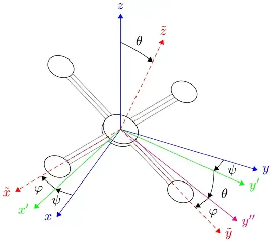
To get another sequence, one can redefine the transformation command as already discussed in this and this answer to the before mentioned question. This way, you can add ultimately all possible sequences and switch between them. In the code below, I used the z-y-x sequence (which are called Tait-Bryan or Cardan angles (see Wikipedia for Euler angles)), since it is closest to the given picture and also the most common for Tait-Byran angles and also a z-x-z sequence as the most common classic Euler angles.
You can then either draw in the main or the rotated coordinate system. This way, it is easy to add any 3D drawing e.g. your drone and also the arcs to mark the angles. The tikz-3dplot package includes a \tdplotdrawarc[coordinates_frame,->,colo]{origin}{radius}{start angle}{end angle}{node info}{label} command but I found it to be more intuitiv to just draw the arc manually on the planes of the rotated coordinate systems with the option canvas is xy plane at z=0 you've already used.
\documentclass[tikz]{standalone}
%\documentclass{article}
\usepackage{tikz}
\usetikzlibrary{arrows.meta, quotes}
%\usetikzlibrary{3d, arrows.meta, calc, quotes}
\usepackage{tikz-3dplot}
% Define new arc command
% Syntax: [draw options] (center) (initial angle:final angle:radius)
% https://tex.stackexchange.com/a/66220
\def\centerarc#1(#3:#4:#5){%
    \draw [#1] ($(#2)+({#5cos(#3)}, {#5sin(#3)})$) arc (#3:#4:#5)%
}
% Redefine the rotation sequence for the tikz3d-plot to Euler-Angles:
% z-x-z with alpha-beta-gamma (psi-theta-phi)
% https://tex.stackexchange.com/q/118069/98906
\newcommand{\tdseteulerzxz}{%
    \renewcommand{\tdplotcalctransformrotmain}{%
        %
        % Determine the sin and cos of the specified angle in degrees
        % \tdplotsinandcos{sin}{cos}{theta}
        % - #1: Returns sin(#3)
        % - #2: Returns cos(#3)
        % - #3: User-specified angle theta
        \tdplotsinandcos{\sinalpha}{\cosalpha}{\tdplotalpha}
        \tdplotsinandcos{\sinbeta}{\cosbeta}{\tdplotbeta}
        \tdplotsinandcos{\singamma}{\cosgamma}{\tdplotgamma}
        %
        % Define trigonometric abbreviations
        %
        \tdplotmult{\sasb}{\sinalpha}{\sinbeta}
        \tdplotmult{\sacb}{\sinalpha}{\cosbeta}
        \tdplotmult{\sacbsg}{\sacb}{\singamma}
        \tdplotmult{\sacbcg}{\sacb}{\cosgamma}
        \tdplotmult{\sasg}{\sinalpha}{\singamma}
        \tdplotmult{\sacg}{\sinalpha}{\cosgamma}
        %
        \tdplotmult{\sbsg}{\sinbeta}{\singamma}
        \tdplotmult{\sbcg}{\sinbeta}{\cosgamma}
        %
        \tdplotmult{\casb}{\cosalpha}{\sinbeta}
        \tdplotmult{\cacb}{\cosalpha}{\cosbeta}
        \tdplotmult{\cacbsg}{\cacb}{\singamma}
        \tdplotmult{\cacbcg}{\cacb}{\cosgamma}
        \tdplotmult{\casg}{\cosalpha}{\singamma}
        \tdplotmult{\cacg}{\cosalpha}{\cosgamma}
        %
        % Define the entries for the rotation matrix from the B-System to the I-System
        % This is A_IB = (A_BI)^T
        %
        \pgfmathsetmacro{\raaeul}{+\cacg - \sacbsg}
        \pgfmathsetmacro{\rabeul}{-\casg - \sacbcg}
        \pgfmathsetmacro{\raceul}{+\sasb}
        %
        \pgfmathsetmacro{\rbaeul}{+\sacg + \cacbsg}
        \pgfmathsetmacro{\rbbeul}{-\sasg + \cacbcg}
        \pgfmathsetmacro{\rbceul}{-\casb}
        %
        \pgfmathsetmacro{\rcaeul}{+\sbsg}
        \pgfmathsetmacro{\rcbeul}{+\sbcg}
        \pgfmathsetmacro{\rcceul}{+\cosbeta}
        %
    }
}
% Redefine the rotation sequence for the tikz3d-plot to Cardan-Angles:
% z-y-x with alpha-beta-gamma
% https://tex.stackexchange.com/q/118069/98906
\newcommand{\tdsetcardanzyx}{%
    \renewcommand{\tdplotcalctransformrotmain}{%
        %
        % Determine the sin and cos of the specified angle in degrees
        % \tdplotsinandcos{sin}{cos}{theta}
        % - #1: Returns sin(#3)
        % - #2: Returns cos(#3)
        % - #3: User-specified angle theta
        \tdplotsinandcos{\sinalpha}{\cosalpha}{\tdplotalpha}
        \tdplotsinandcos{\sinbeta}{\cosbeta}{\tdplotbeta}
        \tdplotsinandcos{\singamma}{\cosgamma}{\tdplotgamma}
        %
        % Define trigonometric abbreviations
        %
        \tdplotmult{\sasb}{\sinalpha}{\sinbeta}
        \tdplotmult{\sasbsg}{\sasb}{\singamma}
        \tdplotmult{\sasbcg}{\sasb}{\cosgamma}
        %
        \tdplotmult{\sacb}{\sinalpha}{\cosbeta}
        \tdplotmult{\sasg}{\sinalpha}{\singamma}
        \tdplotmult{\sacg}{\sinalpha}{\cosgamma}
        %
        \tdplotmult{\casb}{\cosalpha}{\sinbeta}
        \tdplotmult{\casbsg}{\casb}{\singamma}
        \tdplotmult{\casbcg}{\casb}{\cosgamma}
        %
        \tdplotmult{\cacb}{\cosalpha}{\cosbeta}
        \tdplotmult{\casg}{\cosalpha}{\singamma}
        \tdplotmult{\cacg}{\cosalpha}{\cosgamma}
        \tdplotmult{\cbsg}{\cosbeta}{\singamma}
        \tdplotmult{\cbcg}{\cosbeta}{\cosgamma}
        %
        % Define the entries for the rotation matrix from the B-System to the I-System
        % This is A_IB = (A_BI)^T
        %
        \pgfmathsetmacro{\raaeul}{+\cacb}
        \pgfmathsetmacro{\rabeul}{+\casbsg - \sacg}
        \pgfmathsetmacro{\raceul}{+\sasg+\casbcg}
        %
        \pgfmathsetmacro{\rbaeul}{+\sacb}
        \pgfmathsetmacro{\rbbeul}{+\cacg + \sasbsg}
        \pgfmathsetmacro{\rbceul}{\sasbcg-\casg}
        %
        \pgfmathsetmacro{\rcaeul}{-\sinbeta}
        \pgfmathsetmacro{\rcbeul}{+\cbsg}
        \pgfmathsetmacro{\rcceul}{+\cbcg}
        %
    }
}
% Plot display orientation
\tdplotsetmaincoords{50}{115}
\begin{document}
% z-y-x Tait-Bryan angles
\begin{tikzpicture}[scale=2,tdplot_main_coords,> = Triangle]
    % change ratation to z-y-x Tait-Bryan / Cardan angles
    \tdsetcardanzyx
\pgfmathsetmacro{\angpsi}{-20}  % or alpha
\pgfmathsetmacro{\angtheta}{-10}    % or beta
\pgfmathsetmacro{\angphi}{-5}   % or gamma

\pgfmathsetmacro{\r}{2} % unit length radius

\coordinate (O) at (0,0,0);

\tdplotsetrotatedcoords{\angpsi}{\angtheta}{\angphi}
\begin{scope}[tdplot_rotated_coords,scale=1.2]
    \draw coordinate (O) (0,0,-.05) ellipse [radius=.2];
    \foreach \xy/\yx in {x/y, y/x} {
      \fill[white] (xyz cs: \xy = -1, \yx = -.05) -- (xyz cs: \xy =  1, \yx=-.05)
                -- (xyz cs: \xy =  1, \yx =  .05) -- (xyz cs: \xy = -1, \yx= .05) -- cycle;
      \foreach \lmr in {-.05, 0, .05}
        \draw[gray] (xyz cs: \xy=-1, \yx = \lmr) -- (xyz cs: \xy=1, \yx=\lmr);
      \draw[fill=white, radius=.15] (xyz cs: \xy = -1) ellipse[]
                                    (xyz cs: \xy =  1) ellipse[];
    }
    \draw[fill=white] (0,0,0) ellipse [radius=.2];

\end{scope}


% original coordinate system
\foreach \xyz/\Label in {x/left,y/right,z/above}
    \draw[->,blue] (O) -- (xyz cs: \xyz=\r) node[\Label]{$\xyz$};

% angle of first rotation around z-axis
\draw[canvas is xy plane at z=0,->] (1.5,0) arc (0:\angpsi:1.5);
\node at ({1.7*cos(\angpsi/2)},{1.7*sin(\angpsi/2)},0){$\psi$};
\draw[canvas is xy plane at z=0,->] (0,1.5) arc (90:90+\angpsi:1.5);
\node at ({-1.7*sin(\angpsi/2)},{1.7*cos(\angpsi/2)},0){$\psi$};
\tdplotsetrotatedcoords{\angpsi}{0}{0}

% new coordinate system
\begin{scope}[tdplot_rotated_coords]
    \foreach \xyz/\Label in {x/left,y/right}
        \draw[->,green] (O) -- (xyz cs: \xyz=\r) node[\Label]{$\xyz'$};

    % angle of second rotation around new y-axis
    \draw[canvas is xz plane at y=0,->] (1.5,0) arc (0:-\angtheta:1.5);
    \node at ({1.7*cos(\angtheta/2)},0,{-1.7*sin(\angtheta/2)}){$\theta$};
    \draw[canvas is xz plane at y=0,->] (0,1.5) arc (90:90-\angtheta:1.5);
    \node at ({1.7*sin(\angtheta/2)},0,{1.7*cos(\angtheta/2)}){$\theta$};
\end{scope}


\tdplotsetrotatedcoords{\angpsi}{\angtheta}{0}
\begin{scope}[tdplot_rotated_coords]
    \foreach \xyz/\Label in {z/above}
        \draw[->,magenta] (O) -- (xyz cs: \xyz=\r) node[\Label]{$\xyz''$};

    % angle of third rotation around new x-axis
    \draw[canvas is yz plane at x=0,->] (1.5,0) arc (0:\angphi:1.5);
    \node at (0,{1.7*cos(\angphi/2)},{1.7*sin(\angphi/2)}){$\varphi$};
    \draw[canvas is yz plane at x=0,->] (0,1.5) arc (90:90+\angphi:1.5);
    \node at (0,{-1.7*sin(\angphi/2)},{1.7*cos(\angphi/2)}){$\varphi$};
\end{scope}

% rotated coordinate system
\tdplotsetrotatedcoords{\angpsi}{\angtheta}{\angphi}
\begin{scope}[tdplot_rotated_coords]
    \foreach \xyz/\Label in {x/left,y/right,z/above}
        \draw[->,densely dashed,red] (O) -- (xyz cs: \xyz=\r) node[\Label]{$\tilde\xyz$};
\end{scope}

\end{tikzpicture}
% z-x-z Euler angles
\begin{tikzpicture}[scale=2,tdplot_main_coords,> = Triangle]
    % change ratation to z-y-x Tait-Bryan / Cardan angles
    \tdseteulerzxz
\pgfmathsetmacro{\angpsi}{-10}  % or alpha
\pgfmathsetmacro{\angtheta}{-20}    % or beta
\pgfmathsetmacro{\angphi}{-10}  % or gamma

\pgfmathsetmacro{\r}{2} % unit length radius

\coordinate (O) at (0,0,0);

\tdplotsetrotatedcoords{\angpsi}{\angtheta}{\angphi}
\begin{scope}[tdplot_rotated_coords,scale=1.2]
    \draw coordinate (O) (0,0,-.05) ellipse [radius=.2];
    \foreach \xy/\yx in {x/y, y/x} {
      \fill[white] (xyz cs: \xy = -1, \yx = -.05) -- (xyz cs: \xy =  1, \yx=-.05)
                -- (xyz cs: \xy =  1, \yx =  .05) -- (xyz cs: \xy = -1, \yx= .05) -- cycle;
      \foreach \lmr in {-.05, 0, .05}
        \draw[gray] (xyz cs: \xy=-1, \yx = \lmr) -- (xyz cs: \xy=1, \yx=\lmr);
      \draw[fill=white, radius=.15] (xyz cs: \xy = -1) ellipse[]
                                    (xyz cs: \xy =  1) ellipse[];
    }
    \draw[fill=white] (0,0,0) ellipse [radius=.2];

\end{scope}


% original coordinate system
\foreach \xyz/\Label in {x/left,y/right,z/above}
    \draw[->,blue] (O) -- (xyz cs: \xyz=\r) node[\Label]{$\xyz$};

% angle of first rotation around z-axis
\draw[canvas is xy plane at z=0,->] (1.5,0) arc (0:\angpsi:1.5);
\node at ({1.7*cos(\angpsi/2)},{1.7*sin(\angpsi/2)},0){$\psi$};
\draw[canvas is xy plane at z=0,->] (0,1.5) arc (90:90+\angpsi:1.5);
\node at ({-1.7*sin(\angpsi/2)},{1.7*cos(\angpsi/2)},0){$\psi$};
\tdplotsetrotatedcoords{\angpsi}{0}{0}

% new coordinate system
\begin{scope}[tdplot_rotated_coords]
    \foreach \xyz/\Label in {x/left,y/right}
        \draw[->,green] (O) -- (xyz cs: \xyz=\r) node[\Label]{$\xyz'$};

    % angle of second rotation around new x-axis
    \draw[canvas is yz plane at x=0,->] (1.5,0) arc (0:\angtheta:1.5);
    \node at (0,{1.7*cos(\angtheta/2)},{1.7*sin(\angtheta/2)}){$\theta$};
    \draw[canvas is yz plane at x=0,->] (0,1.5) arc (90:90+\angtheta:1.5);
    \node at (0,{-1.7*sin(\angtheta/2)},{1.7*cos(\angtheta/2)}){$\theta$};
\end{scope}


\tdplotsetrotatedcoords{\angpsi}{\angtheta}{0}
\begin{scope}[tdplot_rotated_coords]
    \foreach \xyz/\Label in {y/right}
        \draw[->,magenta] (O) -- (xyz cs: \xyz=\r) node[\Label]{$\xyz''$};

    % angle of third rotation around new z-axis
    \draw[canvas is xy plane at z=0,->] (1.5,0) arc (0:\angphi:1.5);
    \node at ({1.7*cos(\angphi/2)},{1.7*sin(\angphi/2)},0){$\varphi$};
    \draw[canvas is xy plane at z=0,->] (0,1.5) arc (90:90+\angphi:1.5);
    \node at ({-1.7*sin(\angphi/2)},{1.7*cos(\angphi/2)},0){$\varphi$};
\end{scope}

% rotated coordinate system
\tdplotsetrotatedcoords{\angpsi}{\angtheta}{\angphi}
\begin{scope}[tdplot_rotated_coords]
    \foreach \xyz/\Label in {x/left,y/right,z/above}
        \draw[->,densely dashed,red] (O) -- (xyz cs: \xyz=\r) node[\Label]{$\tilde\xyz$};
\end{scope}

\end{tikzpicture}
\end{document}
Results:
Tait-Bryann z-y-x
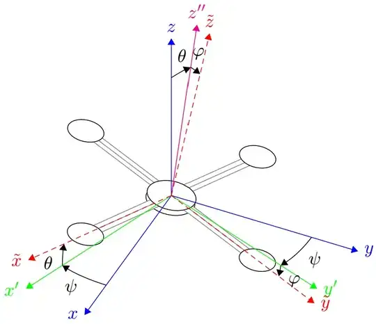 Euler z-x-z