You can find it if you want, but the real answer here is "you don't know". This is why there are so many anchors in circuitikz. For example, for the transistor, several parameters (changed with \ctikzset) influence the size:
(Public) The basic length (bipoles/length), see the manual around page 33, which is the basic, arbitrary length used by all of the package components, by default 1.4 cm;
(Public) The class scale factor (transistors/scale), which will scale the components in its class of the factor specified (it's scoped, so you can apply it to a single transistor), see the manual around page 38, by default 1.0;
(Private) A bunch of internal parameters, some of them relative to the basic length, some of them relative to some other parameter, that define the exact shape¹. In the case of the npn shape, you can find them in the file pgfcirctripoles.tex:
\ctikzset{tripoles/npn/base height/.initial=.45}
\ctikzset{tripoles/npn/base height 2/.initial=.15}
\ctikzset{tripoles/npn/base height/.initial=.4}
\ctikzset{tripoles/npn/conn height/.initial=0}
\ctikzset{tripoles/npn/height/.initial=1.1}
\ctikzset{tripoles/npn/base width/.initial=.5}
\ctikzset{tripoles/npn/arrow pos/.initial=.5}
\ctikzset{tripoles/npn/bodydiode scale/.initial=.3}
\ctikzset{tripoles/npn/bodydiode distance/.initial=.3}
\ctikzset{tripoles/npn/bodydiode conn/.initial=.6}
\ctikzset{tripoles/npn/curr direction/.initial=1}
\ctikzset{tripoles/bjt/npn/curr direction/.initial=1}
You can change them at your own risk (there are just implicit guarantees that they will not change in the future; sometimes it happens, although I always change things so that if you don't touch internal parameters the circuit will not change at least meaning).
Example (using https://tex.stackexchange.com/a/179946/38080):
\documentclass[border=2.72mm,preview]{standalone}
\usepackage{circuitikz}
\makeatletter
\def\extractcoord#1#2#3{
\path let \p1=(#3) in \pgfextra{
\pgfmathsetmacro#1{\x{1}/\pgf@xx}
\pgfmathsetmacro#2{\y{1}/\pgf@yy}
\xdef#1{#1} \xdef#2{#2}
};
}
\makeatother
\begin{document}
\begin{circuitikz}[]
\draw [cyan!50, ultra thin] (-1,-1) grid[step=1mm] (2,1);
\draw [cyan, thin] (-1,-1) grid (2,1);
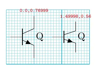
\node [npn](N1) at (0,0) {Q};
\extractcoord\nx\ny{N1.C}
\node [above, red, font=\tiny\ttfamily] at (N1.C) {\nx,\ny};
\ctikzset{tripoles/npn/height=0.8}% internal parameter, beware
\node [npn](N2) at (1.5,0) {Q};
\extractcoord\nx\ny{N2.C}
\node [above, red, font=\tiny\ttfamily] at (N2.C) {\nx,\ny};
\end{circuitikz}
\end{document}
CONCLUSION: Use the anchors, Luke...
Post Data: if you use \ctikzset{bipoles/length=1cm} the numbers are nicer, normally:
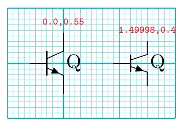
(the 1.49998 is the same as 1.5, given the math precision/resolution of pgfmath).
¹ If I were to rebuild circuitikz from zero, I would do it on a grid. But when I took over the maintenance, one of my promises was to be backward compatible almost forever. The only non-backward compatible bug fix I did is the first FAQ in the manual, which you can also follow here.

