3

I want to build a tree diagram like this one:

enter image description here

I tried with forest package but I got stuck trying to connect two different blue boxes to a grey one.

Here it is what I tried with a more simple example trying to connect R2 and R4 with the same F node:

\begin{forest}
  for tree={
    draw=none,
    edge={-},
    l sep+=7.5pt,
    grow'=180, 
    anchor=north, 
  },
  [I
  [R3
      [C 
        [R1 [A] [B]] 
        [R2 [D] [E] [F]]
    ]
      [H 
        [R4 [F] ]
    ]
    ]
  ]
\end{forest}

I want to connect R2 and R4 nodes to the same F node :/

Maybe I can't do that with forest...

Werner
  • 603,163
felpud0
  • 33
  • 1
    Welcome. I'm sure the forest pros can create such a diagram with forest (mathematically it is a tree after all), though I would use TikZ-CD (i.e. a matrix of nodes and edges) since it is so well structured. How complex will your diagrams get? – Qrrbrbirlbel Jun 17 '23 at 01:17
  • Q574881 and the linked Qs there seem related. – Qrrbrbirlbel Jun 17 '23 at 01:26
  • @Qrrbrbirlbel diagrams can't get much complex but, for example, I could have more than 3 nodes (H,Z,X,Y...) conected to R_4 (always from top). Also, several R_x could be conected to one X (M,V,T,...) node. – felpud0 Jun 17 '23 at 11:43
  • @Qrrbrbirlbel I thought trees had to have single root nodes? Certainly they do in logic tableaux. (The other kind of tree in logic has a single terminal.) To do this in forest you have to use a fake root node, which is a bit fiddly because of the spacing. And then you have to hack the two-parent thing. – cfr Jun 26 '23 at 20:01
  • @cfr Even if it were undirected it contains no cycles so any of them could be the root. But my studies of graph theory are well in the past. The edge direction shouldn't be of concern for TikZ/Forest since that is just a drawing and not a logical thing. – Qrrbrbirlbel Jun 26 '23 at 20:15
  • Also Q213770 is kind of the inverse problem. – Qrrbrbirlbel Jun 26 '23 at 20:15
  • @Qrrbrbirlbel I forgot there were trees in graph theory (about which I know nothing except a little from the TikZ manual). The direction of arrows isn't a concern for forest, but the structure is. forest draws trees in which children have exactly one parent and all nodes are either the root node of descendants of the root. You can fake other structures, but you need hacks of various kinds. (Which is why Gonzalo Medina uses two trees rather than one in that answer and combines them in a third tikzpicture.) – cfr Jun 26 '23 at 20:26

2 Answers2

9

Here's how I'd do it with a matrix using TikZ-CD since your diagram is so well structured.

Code

\documentclass[tikz]{standalone}
\usetikzlibrary{angles, cd}
\tikzset{% helpful styles
  odd rows/.style={/tikz/every odd row/.append style={nodes={#1}}},
  even rows/.style={/tikz/every even row/.append style={nodes={#1}}},
  labels/.style={/tikz/every label/.append style={#1}}}
\tikzcdset{% shortcuts to insert coordinate at start end end
  ms/.style={/tikz/every to/.append style={/tikz/edge node={coordinate[at start](#1)}}},
  me/.style={/tikz/every to/.append style={/tikz/edge node={coordinate[at end](#1)}}},
  mse/.style args={#1:#2}{ms={#1}, me={#2}}}
\begin{document}
\begin{tikzcd}[
  /tikz/labels={minimum size=+1pt, font=\footnotesize},% minimum size to reset
  /tikz/every label quotes/.append style={execute at begin node={FC={}}},
  start anchor=south, end anchor=north,
  cells={nodes={rounded corners, draw, thick}},
  arrows=-Stealth,
  column sep={5em,between origins}, row sep={5em,between origins},
  odd rows={
    fill=gray!50, minimum width=4em, minimum height=2em,
    labels={red!75!black, label position=north}},
  even rows={
    fill=green!50!blue!50, minimum size=3em,
    labels={green!50!blue!50, label position=north east, anchor=north west}},
  execute at end picture={
    \foreach \a in {F--E--D, I--H--G} \pic[draw] {angle/.expanded=\a};}
]
 &     |["0.6"]| C \dar
   & & |["0.5"]| H \dar & \\
 &   |[" 1  "]| R_3 \drar
 & & |["-0.4"]| R_4 \dlar \\
         |["0.6"]| P \drar[mse=D:E]
 & &               T \dlar[ms=F]\drar[mse=G:H]
     & & |["0.3"]| B \dlar[ms=I]\\
 &     |["0.9"]| R_1 \dar
   & & |["0.6"]| R_2 \dar \\
 & M & & V
\end{tikzcd}
\end{document}

Output

enter image description here

Qrrbrbirlbel
  • 119,821
5

Welcome to TeX.SE!!

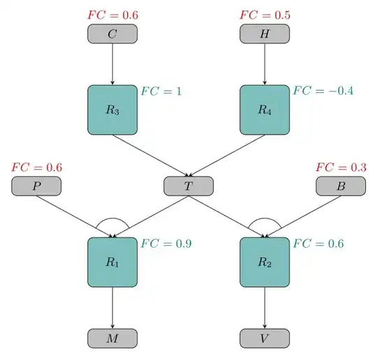
Another approach, this one based in \pics. I made two \pics, one for each type of node. This way we can place the nodes and their labels with the same instruction. As the gray nodes can need or not the red label 'FC', I'm using the conditional \ifblank from etoolbox package.

The code:

\documentclass[tikz,border=1.618mm]{standalone}
\usepackage{etoolbox} % for \ifblank

\tikzset {% pics/gray node/.style 2 args={code=% { \node[draw,fill=gray!50,rounded corners,minimum width=1.3cm,minimum height=0.5cm] (aux) {$#1$}; \ifblank{#2}{}{\node[red] at (0,0.5) {\small$FC=#2$};} \coordinate (-N) at (aux.north); \coordinate (-S) at (aux.south); }}, pics/teal node/.style 2 args={code=% { \node[draw,fill=teal!50,rounded corners,minimum size=1.3cm] (aux) {$#1$}; \node[teal,right] at (0.6,0.5) {\small$FC=#2$}; \coordinate (-N) at (aux.north); \coordinate (-S) at (aux.south); }}, }

\begin{document} \begin{tikzpicture}[font=\small,>=stealth] \pic (AL) at (-2,4) {gray node={C}{0.6}}; \pic (AR) at (2,4) {gray node={H}{0.5}}; \pic (BL) at (-2,2) {teal node={R_3}{1}}; \pic (BR) at (2,2) {teal node={R_4}{-0.4}}; \pic (CL) at (-4,0) {gray node={P}{0.6}}; \pic (T) at (0,0) {gray node={T}{}}; \pic (CR) at (4,0) {gray node={B}{0.3}}; \pic (DL) at (-2,-2) {teal node={R_1}{0.9}}; \pic (DR) at (2,-2) {teal node={R_2}{0.6}}; \pic (EL) at (-2,-4) {gray node={M}{}}; \pic (ER) at (2,-4) {gray node={V}{}}; \foreach\i in {L,R}% left, right { \draw[->] (A\i-S) -- (B\i-N); \draw[->] (B\i-S) -- (T-N); \draw[->] (C\i-S) -- (D\i-N); \draw[->] (T-S) -- (D\i-N); \draw[->] (D\i-S) -- (E\i-N); \begin{scope} \clip (C\i-S) -- (D\i-N) -- (T-S) -- cycle; \draw (D\i-N) circle (0.5); \end{scope} } \end{tikzpicture} \end{document}

enter image description here

Juan Castaño
  • 28,426