4

In the tikzpicture environment, it is simple to create a double-ended arrow with two vertical bars. See the sketch below.

enter image description here

\begin{tikzpicture}
        \draw[|<->|] (-2, 0)--(2, 0);
\end{tikzpicture}

What I'm wondering is, is there a way to create something with arrow heads pointing "outside-in" with whitespace between the two vertical bars like in the sketch below?

enter image description here

This is commonly done in physics diagrams when a length is too small to be indicated in the first way.

Do I have to manually place these bars and arrow heads, or is there a better way? Any comments or ideas would be appreciated.

projetmbc
  • 13,315
Maximal Ideal
  • 217
  • 1
  • 6
  • 1
    like this? \draw[>|-|<] (0, -2)--(0, 2); \draw[white,shorten <=2.1pt,shorten >=2.1pt] (0, -2)--(0, 2); – Black Mild Jun 29 '23 at 21:30
  • @BlackMild Yes. This is very close. Two minor issues: (1) I accidentally mixed up the x and y coords in the OP so I edited my post. (2) we have to offset the coords slightly because changing |<->| to >|-|< displaces the vertical bars slightly. – Maximal Ideal Jun 29 '23 at 21:34
  • How should the vertical bar line up in regards to the specified start and end of the line? See Q111051 – Qrrbrbirlbel Jun 30 '23 at 08:12

5 Answers5

9

Instead of guesstimating the shortening of the line or specifying a sep depending on arrow tip sizes that aren't easy to find out unless you specify them yourself, for the inverted tips I'd place the arrow tips at the start and at the end.

Though, no one wants to place them manually so I suggest the UnMeasure and UnMeasure' styles that use edge nodes. This will need you to use to instead of --.


Note the difference between Measure and Measure' where the Bar actually is placed on the target points instead of just touching it. Instead of a negative sep, one could also load the ext.arrows library and use Untipped Bar.

Code

\documentclass[tikz]{standalone}
\usetikzlibrary{arrows.meta}
\tikzset{
  pics/arrow/.style={/tikz/sloped, /tikz/allow upside down,
    code=\pgfarrowdraw{#1}}, pics/arrow/.default=>,
  Measure/.tip ={Straight Barb[] . Bar[             ]},
  Measure'/.tip={Straight Barb[] . Bar[sep=+0pt +-.5]},
  Measure/.style ={Measure -Measure },
  Measure'/.style={Measure'-Measure'},
  UnMeasure/.style={
    line to, draw=none, arrows=-, % force -- in to, disable drawing and no tips
    every to/.append style={edge node={pic[at start]          {arrow=Measure}
                                       pic[at end, xscale=-1] {arrow=Measure}}}},
  UnMeasure'/.style={
    line to, draw=none, arrows=-, % force -- in to, disable drawing and no tips
    every to/.append style={edge node={pic[at start]          {arrow=Measure'}
                                       pic[at end, xscale=-1] {arrow=Measure'}}}}}
\begin{document}
\begin{tikzpicture}[ultra thick]
\draw[help lines] (-.5,-.5) grid[ystep=.5] (1.5,1.9);
\draw[  Measure ] ( 0, 0  ) -- (1, 0  );
\draw[  Measure'] ( 0,  .5) -- (1,  .5);
\draw[UnMeasure ] ( 0, 1  ) to (1, 1  );
\draw[UnMeasure'] ( 0, 1.5) to (1, 1.5);
\end{tikzpicture}
\end{document}

Output

The second image is achieved by using Straight Barb[angle'=60].

enter image description here enter image description here

Qrrbrbirlbel
  • 119,821
  • I really feel like none of the answers to this post fulfill the "convenient" requirement. is there room for a Tikz library or package to do that, I wonder? – anis Jun 30 '23 at 08:42
  • 2
    @anis, what is "convenient" for you? New library for such unusual and very rear demand? – Zarko Jun 30 '23 at 09:01
  • 2
    @anis Arrow tips are more complicated than they seem (and these are some easy ones), the length of the Straight Barb changes with the angle because of the line join. We could define new tips that “overtip” the line end but the same lengths that define where the tip is drawn is used to place another one behind it, it will get tricky when combining two tips. Depending on how OP wants to use this, I'd package that in a macro or a pic (see dim line) that does the work without the user having to think about using to. – Qrrbrbirlbel Jun 30 '23 at 09:07
  • 1
    @Zarko it's a fairly common way to indicate small dimensions in drawings, where the more common double headed arrow with bars won't fit. Of course that might not make it common enough to include in a library – Chris H Jun 30 '23 at 09:07
  • @ChrisH, yes what you say, but this is ate technical drawing (at least in time when I learn it in school) done on different way. Not just draw arrows heads ... – Zarko Jun 30 '23 at 09:18
  • @Zarko in true engineering drawing, yes (and for that I'd use a CAD package anyway). Some ideas from that carry over to detailed, dimensioned, diagrams, which is what I guess the OP is doing. – Chris H Jun 30 '23 at 09:45
  • 1
    To OP and @anis: How more convenient can it get? Yes, a proper arrow tip thingy would be nice but I think this is the next best option. – Qrrbrbirlbel Jun 30 '23 at 12:40
  • 1
    @Qrrbrbirlbel you clearly answered my question. I find your approach convenient enough. I understand that creating a package for the tikz style is pointless. I was just wondering why it is always complicated to manipulate arrows. it is among the most verbose concepts of Tikz, to me. – anis Jun 30 '23 at 12:51
7

This exploits that the arrows reset the dash pattern. This allows one to make the line between the arrow heads disappear. In addition, one can reverse the arrow heads of the arrows.meta library easily.

\documentclass[tikz,border=2mm]{standalone}
\usetikzlibrary{arrows.meta}
\begin{document}
\begin{tikzpicture}
    \draw[{Straight Barb[reversed].Bar[]}-{Bar[].Straight Barb[reversed]},dash pattern=on 0pt off 500pt]
    (-2, 0)--(2, 0);
\end{tikzpicture}    
\end{document}

enter image description here

Obviously you can change the appearance of the arrow heads, make this as style, and so on.

6

With arrows.meta

\documentclass{article}
\usepackage{tikz}
\usetikzlibrary {arrows.meta}
\begin{document}
  \tikz{
    \draw[help lines](0,-1)grid(4,2);
    \draw [{Stealth[length=4pt]}-{Stealth[length=4pt]}] (0,1) -- (4,1);
    \draw [draw=none,tips=true,{Stealth[length=4pt,reversed]}-{Stealth[length=4pt,reversed]},shorten <=-4pt,shorten >=-4pt] (0,0) -- (4,0);
  }
\end{document}

EDIT: with the Chris H.'s comment, but a much less successful solution than that of Qrrbrbirlbel. In particular the shorten >=-3pt

\documentclass{article}
\usepackage{tikz}
\usetikzlibrary {arrows.meta}
\begin{document}
\tikzset{
  mytips/.tip = {Straight Barb[length=2pt]},
  mytipsrev /.tip = {Straight Barb[length=2pt,reversed]},
  myarrow/.style = {{mytips}-{mytips}},
  myarrowreverse/.style = {draw=none,tips=true,{mytipsrev}|-|{mytipsrev},shorten <=-3pt,shorten >=-3pt},
}

\begin{tikzpicture} \drawhelp linesgrid(4,2); \draw [myarrow] (0,1) -- (4,1); \draw [myarrowreverse] (0,0) -- (4,0); \end{tikzpicture} \end{document}

enter image description here

pascal974
  • 4,652
  • with arrows.meta can't you double up and use an arrow-shaped arrowhead as well as a bar to get the line the OP has sketched as well? I haven't tried it myself. – Chris H Jun 30 '23 at 09:12
  • @Chris H, I edited my answer (it's far from perfect). – pascal974 Jun 30 '23 at 10:59
4

Oh, we should not write a new library for such trivial task!

There is a simple way with plain TikZ, that is, using suitable pics (small picture on paths). The option sloped is necessary, and

pic[sloped,pos=0]{tipL} pic[sloped,pos=1]{tipR}

works as desired.

enter image description here

\documentclass[tikz,border=5mm]{standalone}
\begin{document}
\begin{tikzpicture}
[tipR/.pic={\draw (45:.2)--(0,0)--(-45:.2) (0,.2)--(0,-.2);},
 tipL/.pic={\draw (135:.2)--(0,0)--(-135:.2) (0,.2)--(0,-.2);}
]
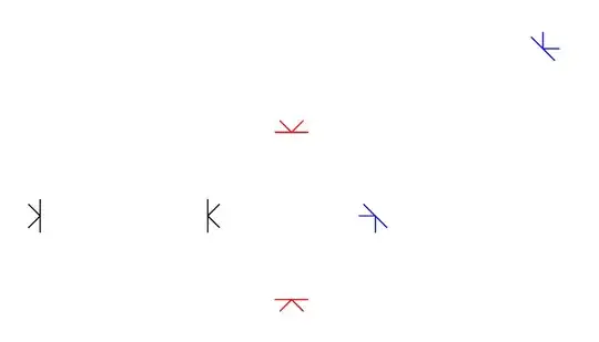
\path       (0,0)--(2,0)  pic[sloped,pos=0]{tipL} pic[sloped,pos=1]{tipR};
\path[red]  (3,-1)--(3,1) pic[sloped,pos=0]{tipL} pic[sloped,pos=1]{tipR};
\path[blue] (4,0)--+(2,2) pic[sloped,pos=0]{tipL} pic[sloped,pos=1]{tipR};
\end{tikzpicture}
\end{document}

PS: To make the tip of arrows just touching the bars, we may use xshift=-\pgflinewidth

enter image description here

\documentclass[tikz,border=5mm]{standalone}
\begin{document}
\begin{tikzpicture}
\tikzset{
tipR/.pic={\draw[xshift={\pgflinewidth}] (45:.2)--(0,0)--(-45:.2); 
           \draw (0,.2)--(0,-.2);},
tipL/.pic={\draw[xshift={-\pgflinewidth}] (135:.2)--(0,0)--(-135:.2);
           \draw (0,.2)--(0,-.2);}
}

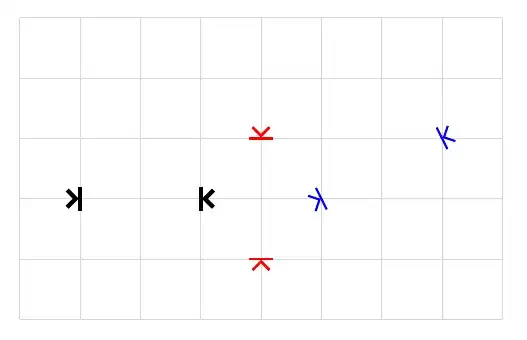
\draw[gray!30] (-1,-2) grid (7,3); \def\mypictip{pic[sloped,pos=0]{tipL} pic[sloped,pos=1]{tipR}}

\path[line width=2pt] (0,0)--(2,0) \mypictip; \path[red,very thick] (3,-1)--(3,1) \mypictip; \path[blue,line width=1pt] (4,0)--+(2,1) \mypictip; \end{tikzpicture} \end{document}

Black Mild
  • 17,569
1

My attempt so far as been to write the following:

\begin{tikzpicture}
    \draw[->|] (-2.01, 0)--(-2, 0);
    \draw[->|] (2.01, 0)--(2, 0);
\end{tikzpicture}

Alternatively, Black Mild in the comments suggested

\draw[>|-|<] (-2, 0)--(2, 0);   
\draw[white,shorten <=2.1pt,shorten >=2.1pt] (-2, 0)--(2, 0);

However, this second suggestion would require you to manually adjust the positions of the arrow tips since the vertical bars will be displaced when you change from >|-|< to |<->|. Nonetheless this is still an interesting suggestion that I think can be helpful.

Maximal Ideal
  • 217
  • 1
  • 6