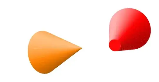
The code is long since I defined a general cone in the light as a pic object. It depends on eight arguments: the centers of the bottom and top faces (6 arguments) and the two corresponding radii.
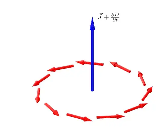
Based on this element, a solid arrow is constructed also as a pipc object. This time there are only six arguments (#4 is always "empty'). But there are two keys that control the arrow's aspect and that can be modified: arrowhead and arrow radius. In the example they are both modified for the blue arrow.
Remark
I insert some cones that can be drawn with the cone object. Maybe somebody finds them useful.
The code
\documentclass[11pt, margin=15pt]{standalone}
\usepackage{tikz}
\usetikzlibrary{math}
\begin{document}
\tikzset{%
  view/.style 2 args={%  observer longitude and latitude (y upwards)
                      %  Remark. lomg=0 means x=0
    z={({-sin(#1)}, {-cos(#1)sin(#2)})},
    x={({cos(#1)}, {-sin(#1)sin(#2)})},
    y={(0, {cos(#2)})},
    evaluate={%
      \tox={sin(#1)cos(#2)};
      \toy={sin(#2)};
      \toz={cos(#1)cos(#2)};
    },
    longitude = #1,
    latitude = #2
  },
  sun/.style n args={3}{% longitude, latitude, light contrast in [0, 1]
    sun longitude = #1,
    sun latitude = #2,
    contrast = #3,
    evaluate={%
      real \sunx, \suny, \sunz, \lightC;
      \sunx = sin(\sLongit)cos(\sLatit);
      \suny = sin(\sLatit);
      \sunz = cos(\sLongit)cos(\sLatit);
    }
  }
}
\pgfkeys{/tikz/.cd,
  latitude/.store in=\aLatit,  % observer's latitude
  latitude=0
}
\pgfkeys{/tikz/.cd,
  longitude/.store in=\aLongit,  % observer's longitude
  longitude=0  % corresponds to x=0
}
\pgfkeys{/tikz/.cd,
  sun latitude/.store in=\sLatit,
  sun latitude = 80
}
\pgfkeys{/tikz/.cd,
  sun longitude/.store in=\sLongit,
  sun longitude=90
}
\pgfkeys{/tikz/.cd,
  contrast/.store in=\lightC,  % light contrast \in [0, 1]
  contrast=.5
}
\pgfkeys{/tikz/.cd,
  arrowhead/.store in=\arrowLConstant,  % proportion of the head \in [0, 1]
  arrowhead=.3
}
\pgfkeys{/tikz/.cd,
  arrow radius/.store in=\arrowRadius,  % body radius in cm
  arrow radius=.08
}
\tikzmath{%
  function coneBaseColor(\k) {% \k = 1 or 2 for the two disks: bottom top
    \res = \nx\tox + \ny\toy + \nz\toz;
    if \k==1 then {% bottom; the normal vector is -n
      \res = -\res;
    };
    if \res>0 then {% if seen
      \tmp = int(100\lightC(\nx\sunx + \ny\suny + \nz\sunz));
      if \k==1 then {return -\tmp;} else {return \tmp;};
    } else {return -1000;};
  };
  function coneFaceColor(\j, \M) {% verifies if seen
    real \ang;
    \t = 360((\j-.5)/\M);
    \ux = \vxcos(\t) +\wxsin(\t);
    \uy = \vycos(\t) +\wysin(\t);
    \uz = \vzcos(\t) +\wzsin(\t);
    % modification needed when the radii are different
    \ang = atan2(\coneRadiusB -\coneRadiusT, \tmpAB);
    \ux = \uxcos(\ang) +\nxsin(\ang);
    \uy = \uycos(\ang) +\nysin(\ang);
    \uz = \uzcos(\ang) +\nzsin(\ang);

    \res = \ux\tox + \uy\toy + \uz\toz;
    if \res>0 then {% if seen
      \tmp = int(100\lightC(\ux\sunx + \uy\suny + \uz*\sunz));
      return \tmp;
    } else {return -1000;};
  };

}
\tikzset{%
  pics/cone/.style args={(#1,#2,#3), (#4,#5,#6), rB=#7, rT=#8}{%
    % x, y, z of the bottom and top centers, bottom and top radius
    code={%

      \colorlet{mainColor}{.}
      \colorlet{leftRGB{1}}{white}
      \colorlet{leftRGB{0}}{mainColor!50!black}
      \colorlet{mainDark}{mainColor!50!black}
      \tikzmath{%  A, B, rB, rT, and construction of the orthonormal basis
        real \Ax, \Ay, \Az, \Bx, \By, \Bz, \coneRadiusB, \coneRadiusT;
        \Ax = #1;
        \Ay = #2;
        \Az = #3;
        \Bx = #4;
        \By = #5;
        \Bz = #6;
        \coneRadiusB = #7;
        \coneRadiusT = #8;
        integer \coneN, \k, \j, \prevj, \i;
        \coneN = 13 +int(max(40#7, 40#8));
        real \tmpAB, \tmpx, \tmpy, \tmpz, \tmpcst, \tmpForColor;
        real \nx, \ny, \nz, \vx, \vy, \vz, \wx, \wy, \wz;
        \tmpx = \Bx -\Ax;
        \tmpy = \By -\Ay;
        \tmpz = \Bz -\Az;
        \tmpAB = sqrt(\tmpx\tmpx +\tmpy\tmpy +\tmpz\tmpz);
        \nx = \tmpx/\tmpAB;
        \ny = \tmpy/\tmpAB;
        \nz = \tmpz/\tmpAB;
        if abs(\ny)>=abs(\nz) then {%
          \tmpcst = sqrt(\nx\nx +\ny\ny);
          \vx = -\ny/\tmpcst;
          \vy = \nx/\tmpcst;
          \vz = 0;
          \wx = -\vy\nz;
          \wy = \vx\nz;
          \wz = (1 -\nz\nz)/\tmpcst;
        } else {%
          \tmpcst = sqrt(\nx\nx +\nz\nz);
          \vx = -\nz/\tmpcst;
          \vy = 0;
          \vz = \nx/\tmpcst;
          \wx = \vz\ny;
          \wy = (\ny\ny -1)/\tmpcst;
          \wz = -\vx\ny;
        };
        %% points \P {1,\j} for bottom, \P {2,\j} for top
        for \j in {0, ..., \coneN}{%
          \t = \j/\coneN360;
          \Px{1,\j} = \Ax +\coneRadiusB\vxcos(\t) +\coneRadiusB\wxsin(\t);
          \Py{1,\j} = \Ay +\coneRadiusB\vycos(\t) +\coneRadiusB\wysin(\t);
          \Pz{1,\j} = \Az +\coneRadiusB\vzcos(\t) +\coneRadiusB\wzsin(\t);
          \Px{2,\j} = \Bx +\coneRadiusT\vxcos(\t) +\coneRadiusT\wxsin(\t);
          \Py{2,\j} = \By +\coneRadiusT\vycos(\t) +\coneRadiusT\wysin(\t);
          \Pz{2,\j} = \Bz +\coneRadiusT\vzcos(\t) +\coneRadiusT\wzsin(\t);
        };
        %% lateral faces
        for \j in {1, ..., \coneN}{%
          \prevj = \j -1;
          \tmpForColor = coneFaceColor(\j, \coneN);
          if \tmpForColor>-999 then {%
            if \tmpForColor>=0. then { \i = 1; } else {%
              \i = 0;  % in the shade for leftRGB{}
              \tmpForColor = int(abs(\tmpForColor));
            };
            {%
              \filldraw[leftRGB{\i}!\tmpForColor!mainColor, line width=.001pt]
              (\Px{1,\prevj}, \Py{1,\prevj}, \Pz{1,\prevj})
              -- (\Px{1,\j}, \Py{1,\j}, \Pz{1,\j})
              -- (\Px{2,\j}, \Py{2,\j}, \Pz{2,\j})
              -- (\Px{2,\prevj}, \Py{2,\prevj}, \Pz{2,\prevj})
              -- cycle;
            };

          };
        };
        %% bottom or top face
        for \k in {1, 2}{
          \tmpForColor = coneBaseColor(\k);
          if \tmpForColor>-999. then {%
            if \tmpForColor>=0. then { \i = 1; } else {%
              \i = 0;  % in the shade for leftRGB{}
              \tmpForColor = int(abs(\tmpForColor));
            };
            {
              \fill[leftRGB{\i}!\tmpForColor!mainColor]
              (\Px{\k,0}, \Py{\k,0}, \Pz{\k,0})
              \foreach \j in {1, ..., \coneN}{%
                -- (\Px{\k,\j}, \Py{\k,\j}, \Pz{\k,\j})
              } -- cycle;
           };
          };
        };
      }  % end tikzmath
    }
  },
  pics/solid arrow/.style args={(#1,#2,#3)--#4+(#5,#6,#7)}{%
    code={%
      \colorlet{arrowColor}{.}
      \tikzmath{%
        real \aVx, \aVy, \aVz;
        \aVx = #5;
        \aVy = #6;
        \aVz = #7;
        real \CyBx, \CyBy, \CyBz, \Mx, \My, \Mz, \CoTx, \CoTy, \CoTz;
        \CyBx = #1;
        \CyBy = #2;
        \CyBz = #3;
        \CoTx = \CyBx +\aVx;
        \CoTy = \CyBy +\aVy;
        \CoTz = \CyBz +\aVz;
        \Mx = \CyBx +(1 -\arrowLConstant)\aVx;
        \My = \CyBy +(1 -\arrowLConstant)\aVy;
        \Mz = \CyBz +(1 -\arrowLConstant)\aVz;
        real \cylinderRadius, \coneRadius, \arrowL;
        \arrowL = sqrt(\aVx\aVx +\aVy\aVy +\aVz\aVz);
        \cylinderRadius = \arrowRadius;
        \coneRadius = 2\cylinderRadius;
        \testTopSeen = \aVx\tox + \aVy\toy + \aVz\toz;
        if \testTopSeen>0 then {%
          {
            \draw pic[arrowColor]
            {cone={(\CyBx, \CyBy, \CyBz), (\Mx, \My, \Mz),
                rB=\cylinderRadius, rT=\cylinderRadius}};
            \draw pic[arrowColor]
            {cone={(\Mx, \My, \Mz), (\CoTx, \CoTy, \CoTz),
                rB=\coneRadius, rT=0}};
          };
        } else {%
          {
            \draw pic[arrowColor]
            {cone={(\Mx, \My, \Mz), (\CoTx, \CoTy, \CoTz),
                rB=\coneRadius, rT=0}};
            \draw pic[arrowColor]
            {cone={(\CyBx, \CyBy, \CyBz), (\Mx, \My, \Mz),
                rB=\cylinderRadius, rT=\cylinderRadius}};
          };
        };
      }  % end tikzmath
    }
  }
}
\begin{tikzpicture}[view={20}{30}, sun={-110}{30}{.5},
  arrow radius=.07,
  evaluate={%
    real \r, \l;
    \r = 3; \l = 1.6;
    integer \N;
    \N = 11;
  }]
  \foreach \k [evaluate=\k as \t using {90 +(\k/\N)360}]
  in {1, ..., \N}{%
    \path pic[red]
    {solid arrow={({\rsin(\t)}, 0, {\rcos(\t)})--
        +({\lcos(\t)}, 0, {-\lsin(\t)})}};
  }
  \path pic[blue, arrow radius=.075, arrowhead=.17]
  {solid arrow={(0, 0, 0)-- +(0, 3\l, 0)}};
\path (0, 0, 0) +(0, 3*\l, 0)
  node[right=1ex] {$\vec{J}+\frac{\partial\vec{D}}{\partial t}$};;
\end{tikzpicture}
\end{document}


Coneyou introduced, but I understand that there are two behaviors depending on whether the vertex is visible. A possibility to suggest the position in space would be to add a white line along the arrow's body (suggesting a highlight) and then to add a similar line on the cone only when visible. For consistency, all those lines must appear near the top part of each arrow... This is the point where the definition of the body of the arrow is important. – Daniel N Sep 24 '23 at 23:56picelement instead to be a solid arrow (depending on the initial and end points of the desired arrow). And it will take some time... a week say. Anyway, in my opinion, to have coherent highlights in a 3d image the observer's point of view and the light source's position must be given (defined). – Daniel N Sep 25 '23 at 09:12