The to-path handler of circuitikz does not handle curved wires. Although I understand sometimes they can be helpful, they raise the complexity too much (at least in the case of a path with a component in the middle). For wires, TikZ has the needed tools. This is an example:
\documentclass[border=10pt]{standalone}
\usepackage[T1]{fontenc}
\usepackage[siunitx, RPvoltages]{circuitikz}
% get the circuitikz arrow size, define a tip https://tex.stackexchange.com/a/549354/38080
\makeatletter
\newdimen\ctikzAL\newdimen\ctikzAW
\pgfmathsetlength{\ctikzAL}{ 1.7 * \pgf@circ@Rlen / \ctikzvalof{current arrow scale} + 2*\pgflinewidth}
\pgfmathsetlength{\ctikzAW}{ 1.6 * \pgf@circ@Rlen / \ctikzvalof{current arrow scale} + 2*\pgflinewidth}
\tikzset{c>/.tip={Triangle[length=\the\ctikzAL, width=\the\ctikzAW]}}
\makeatother
% See https://tex.stackexchange.com/a/39282/38080
\usetikzlibrary{decorations.markings}
\tikzset{->-/.style={decoration={
markings,
mark=at position 0.5 with {\arrow{c>}}},postaction={decorate}}}
\begin{document}
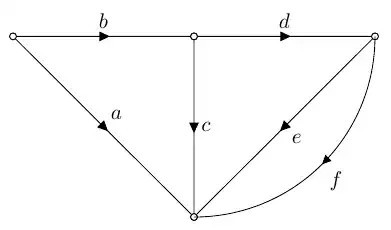
\begin{tikzpicture}[]
\draw (0,3) to[short,i>=$b$, o-o] (3,3) to[short,i>=$d$, o-o] (6,3);
\draw (0,3) to[short,i>=$a$, o-o] (3,0);
\draw (3,3) to[short,i>=$c$, o-o] (3,0);
\draw (6,3) to[short,i>=$e$, o-o] (3,0);
% see https://tikz.dev/tutorial-nodes#sec-3.11
\draw[->-] (6,3) to[out=-90, in=0] node[auto]{$f$} (3, 0);
\end{tikzpicture}
\end{document}
References: Circuitikz Arrowhead, Tikz: Arrowheads in the center, https://tikz.dev/tutorial-nodes#sec-3.11
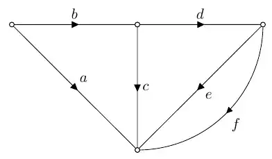
As you can see, the final wires start from the center of the "poles", as explained in the circuitikz manual in section 6.1. In this case, you can solve it by simply drawing the bent thing before the rest and relying on pole filling.
\begin{tikzpicture}[]
    % see https://tikz.dev/tutorial-nodes#sec-3.11
    \draw[->-] (6,3) to[out=-90, in=0] node[auto]{$f$} (3, 0);
    \draw (0,3) to[short,i>=$b$, o-o] (3,3) to[short,i>=$d$, o-o] (6,3);
    \draw (0,3) to[short,i>=$a$, o-o] (3,0);
    \draw (3,3) to[short,i>=$c$, o-o] (3,0);
    \draw (6,3) to[short,i>=$e$, o-o] (3,0);
\end{tikzpicture}


to-path commands ofcircuitikzonly support straight lines, sorry. The solution is using decorations, like in https://tex.stackexchange.com/questions/39278/tikz-arrowheads-in-the-center – Rmano Nov 24 '23 at 22:30