Not really answering the question of how to properly attach arrow heads to decorated paths and probably not the most straight-forward way to solve this, but you could make use of a \pic and draw the paths using the sin and cos operators:
\documentclass[border=10pt]{standalone}
\usepackage{tikz}
\usetikzlibrary{arrows.meta}
\tikzset{
    >={Latex},
    solid node/.style={
        circle,
        fill,
        inner sep=1.25pt,
    },
    pics/sine wave/.style={
        code={
            \tikzset{sine wave/.cd, #1}
            \coordinate[at={\pgfkeysvalueof{/tikz/sine wave/from}}] (-from);
            \coordinate[at={\pgfkeysvalueof{/tikz/sine wave/to}}] (-to);
            \path (-from); \pgfgetlastxy{\startx}{\starty}
            \path (-to); \pgfgetlastxy{\endx}{\endy}
            \pgfmathsetmacro{\currentpathlength}{sqrt((\endx-\startx)^2+(\endy-\starty)^2)}
            \pgfmathsetmacro{\currentpathrotate}{atan2((\endy-\starty),(\endx-\startx))}
            \pgfmathsetmacro{\segmentlength}{\currentpathlength/\pgfkeysvalueof{/tikz/sine wave/frequency}/4}
            \pgfmathsetmacro{\segmentheight}{\pgfkeysvalueof{/tikz/sine wave/amplitude}/2}
            \pgfmathsetmacro{\frequencyint}{int(\pgfkeysvalueof{/tikz/sine wave/frequency})}
            \pgfmathsetmacro{\isinteger}{\pgfkeysvalueof{/tikz/sine wave/frequency}==\frequencyint?1:0)}
            \draw[rotate={\currentpathrotate}, pic actions] (-from)
                \foreach \n in {1,...,\frequencyint} {
                    sin +({\segmentlength1pt},{\segmentheight})
                    cos +({\segmentlength1pt},{-1\segmentheight})
                    sin +({\segmentlength1pt},{-1\segmentheight})
                    cos +({\segmentlength1pt},{\segmentheight})
                }
                \ifnum\isinteger=1\else
                    sin +({\segmentlength1pt},{\segmentheight})
                    cos +({\segmentlength1pt},{-1*\segmentheight})
                \fi;
        }
    },
    sine wave/from/.initial={(0,0)},
    sine wave/to/.initial={(1,0)},
    sine wave/frequency/.initial={1},
    sine wave/amplitude/.initial={0.25}
}
\begin{document}
    \begin{tikzpicture}
        \node (1) [solid node,label=left:{$1$}] at (0,3){};
        \node (i) [solid node,label=above:{$i$}] at (3,3){};
        \node (j) [solid node,label=left:{$j$}] at (2,0.3){};
        \node (n) [solid node,label=right:{$n$}] at (5,0){};
        \draw[densely dashed, ->, bend left=20] (j) to (i);
        \draw[densely dashed, ->, bend left=20] (i) to (j);
        \path (1) -- (i) node[midway, below=5pt] {$c$};
        \pic[->] {sine wave={from={(1)}, to={(i)}, frequency={3.5}}};
        \path (j) -- (n) node[midway, below=5pt] {$c$};
        \pic[->] {sine wave={from={(j)}, to={(n)}, frequency={2.5}, amplitude={-0.33}}};
    \end{tikzpicture}
\end{document}
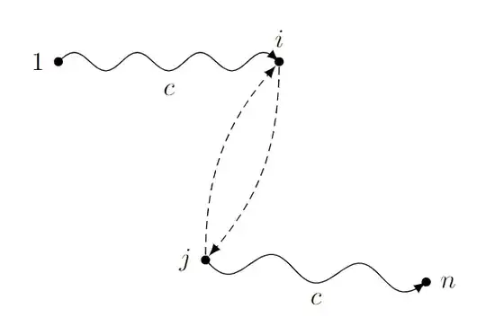
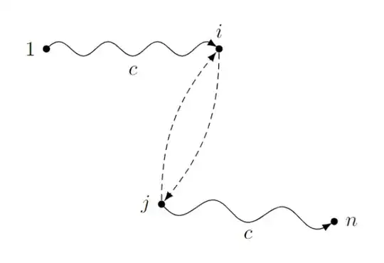
Sadly, this way the arrow heads don't really end at the border of the node shapes. You would need to manually adjust this (as we know the size of the circles due to inner sep=1.25pt, we can use shorten >=1.25pt here). You could also add the bending library to provide for bending arrow heads:
\documentclass[border=10pt]{standalone}
\usepackage{tikz}
\usetikzlibrary{arrows.meta, bending}
\tikzset{
    >={Latex[flex]},
    solid node/.style={
        circle,
        fill,
        inner sep=1.25pt,
    },
    pics/sine wave/.style={
        code={
            \tikzset{sine wave/.cd, #1}
            \coordinate[at={\pgfkeysvalueof{/tikz/sine wave/from}}] (-from);
            \coordinate[at={\pgfkeysvalueof{/tikz/sine wave/to}}] (-to);
            \path (-from); \pgfgetlastxy{\startx}{\starty}
            \path (-to); \pgfgetlastxy{\endx}{\endy}
            \pgfmathsetmacro{\currentpathlength}{sqrt((\endx-\startx)^2+(\endy-\starty)^2)}
            \pgfmathsetmacro{\currentpathrotate}{atan2((\endy-\starty),(\endx-\startx))}
            \pgfmathsetmacro{\segmentlength}{\currentpathlength/\pgfkeysvalueof{/tikz/sine wave/frequency}/4}
            \pgfmathsetmacro{\segmentheight}{\pgfkeysvalueof{/tikz/sine wave/amplitude}/2}
            \pgfmathsetmacro{\frequencyint}{int(\pgfkeysvalueof{/tikz/sine wave/frequency})}
            \pgfmathsetmacro{\isinteger}{\pgfkeysvalueof{/tikz/sine wave/frequency}==\frequencyint?1:0)}
            \draw[rotate={\currentpathrotate}, pic actions] (-from)
                \foreach \n in {1,...,\frequencyint} {
                    sin +({\segmentlength1pt},{\segmentheight})
                    cos +({\segmentlength1pt},{-1\segmentheight})
                    sin +({\segmentlength1pt},{-1\segmentheight})
                    cos +({\segmentlength1pt},{\segmentheight})
                }
                \ifnum\isinteger=1\else
                    sin +({\segmentlength1pt},{\segmentheight})
                    cos +({\segmentlength1pt},{-1*\segmentheight})
                \fi;
        }
    },
    sine wave/from/.initial={(0,0)},
    sine wave/to/.initial={(1,0)},
    sine wave/frequency/.initial={1},
    sine wave/amplitude/.initial={0.25}
}
\begin{document}
    \begin{tikzpicture}
        \node (1) [solid node,label=left:{$1$}] at (0,3){};
        \node (i) [solid node,label=above:{$i$}] at (3,3){};
        \node (j) [solid node,label=left:{$j$}] at (2,0.3){};
        \node (n) [solid node,label=right:{$n$}] at (5,0){};
        \draw[densely dashed, ->, bend left=20] (j) to (i);
        \draw[densely dashed, ->, bend left=20] (i) to (j);
        \path (1) -- (i) node[midway, below=5pt] {$c$};
        \pic[->, shorten >=1.25pt] {sine wave={from={(1)}, to={(i)}, frequency={3.5}}};
        \path (j) -- (n) node[midway, below=5pt] {$c$};
        \pic[->, shorten >=1.25pt] {sine wave={from={(j)}, to={(n)}, frequency={2.5}, amplitude={-0.33}}};
    \end{tikzpicture}
\end{document}


sinandcosoperators maybe. – Jasper Habicht Dec 02 '23 at 19:23markingslibrary wherebendingwouldn't help anyway) you can see that there is a short straight segment at the end because thesegment lengthdoesn't fit integer times into the path length. PGF then just fills up the rest with a straight part, and then the arrow is placed at the end of this straight part. It will always look that way then. I think you want a different decoration. (And don't place arrowsat position 1.) – Qrrbrbirlbel Dec 02 '23 at 22:06