The code from the linked answer below is included in the positioning-plus library which is used in the second example for more than what the linked answer provides.
The alignment problem has two reasons:
- The
matrix of nodes style sets the anchor of every node in the matrix to base (which is usually what you want).
- The empty cells are empty and thus the baseline of the empty text box is at the same height as the center of the node and thus will be aligned a little bit lower.
This can be reverted by using the center anchor again, though this will fail if all node texts do not have the same height and depth (something similar will happen if one of the node’s text is wider than <minimum width> - 2 <inner xsep>). For normal one-lined text you can fix this with a \strut in every node, applied by the font key.
For the multi-columns and multi-rows I actually would set nodes in empty cells to false and use a not-drawn node (so that it can used later as a reference but is not seen). Instead of fit, I’d use my span key from another answer of mine to TikZ: Make node height span several others. The span style only sets the correct minimum widths and minimum heights, the location must been set with at (fit bounding box), a pseude-node created by the span key. As it doesn’t change text depth or text height the vertical position of the text is not changed.
Code
\documentclass[tikz,convert=false]{standalone}
\usepackage{lmodern}
\usetikzlibrary{matrix, positioning-plus}
\tikzset{
  block/.style={
    rectangle,
    draw,
    minimum height=4em,
    minimum width=4em,
    outer sep=0pt,
%    anchor=center,
    font=\strut},
  empty cells are empty/.style={
    execute at empty cell={\node[draw=none,fill=none]{};},
    nodes in empty cells=false
  },
  overlapping lines in matrices/.style={
    row sep=-\pgflinewidth,
    column sep=-\pgflinewidth}
}
\begin{document}
\begin{tikzpicture}
    \matrix (table) [%
      matrix of nodes,
      ampersand replacement=\&,
      nodes=block,
      overlapping lines in matrices,
      empty cells are empty
    ] {%
      A \& B \& C \& D \\
      e \&   \&   \& G \\
      H \& I \& J \&   \\
      K \& L \& M \&   \\
   };
    \node[block, span=(table-2-2)(table-2-3)] at (fit bounding box) {F};
    \node[block, span=(table-3-4)(table-4-4)] at (fit bounding box) {N};
\end{tikzpicture}
\end{document}
Output

For your other diagram, I again advise against fit and a manual adjustment with xshift and yshift. It would be better to use the positioning library with its node distance key (<vertical distance> and <horizontal distance> is the syntax).
For the first code example, the nodes b, c and d are placed in a horizontal fashion with right=of <previous node> (the chains library can help with the creation of many nodes). The positioning keys are again improved with the code from the linked answer above, so that you can use below=of -(b)(d) which means that the new node will be created below b and d and with a minimal width such that it spans both nodes horizontally.
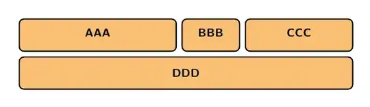
The second example places first the a node and then the nodes b and d are placed above of a but west- and east-aligned, thus the keys are west above and east above. These keys are provided by my positioning-plus library.
Much as above sets the own anchor to south while the referenced node’s anchor is set to north, west above sets the own anchor to north west and the referenced node’s anchor to south west. An overview of the positioning keys can be seen in another answer of mine.
The fourth node c is then simply placed between the borders of b and d. This does not check the minimum widths for validity nor does it use the horizontal node distance.
Code
\documentclass[tikz,convert=false]{standalone}
\usepackage{lmodern}
\usetikzlibrary{positioning-plus}
\tikzset{
  node distance=+2mm and +2mm,
  every node/.style={
    rectangle,
    rounded corners=1mm,
    very thick,
    draw,
    fill=orange!50
  }
}
\begin{document}
\begin{tikzpicture}% Code A
  \node[minimum width=+.3\textwidth]  (b) {B};
  \node[minimum width=+.07\textwidth, right=of b] (c) {C};
  \node[minimum width=+.2\textwidth, right=of c] (d) {D};
  \node[below=of -(b)(d)] (a) {AAAA};
\end{tikzpicture}
\begin{tikzpicture}% Code B
  \node[minimum width=.6\textwidth] (a) {AAAA};
  \node[minimum width=+.3\textwidth, west above=of a] (b) {B};
  % or: \node[minimum width=+.3\textwidth, above=of a.north west, anchor=south west] (b) {B};
  \node[minimum width=+.2\textwidth, east above=of a] (d) {D};
  % or: \node[minimum width=+.2\textwidth, above=of a.north east, anchor=south east] (d) {D};
  \path (b) -- node[minimum width=+.07\textwidth] (c) {C} (d);% places the node (c) in the
                                                              % middle between (b) and (d)
\end{tikzpicture}
\end{document}
Output
Output A

Output B


nodes={...}in the matrix without any hassle with struts – percusse Jul 20 '13 at 01:31west above=of a(formpositioning-plus) is equivalent toabove=of a.north west,anchor=south west... – Paul Gaborit Jul 20 '13 at 08:04