Consider the following MWE:
\documentclass[%
12pt,
journal,
onecolumn,
twoside,
draftcls,
letterpaper,
]{IEEEtran}
\usepackage{tikz}
\usetikzlibrary{calc}
\usetikzlibrary{positioning}
\usetikzlibrary{3d}
\usepackage{adjustbox}
\usepackage{setspace} %\singlespacing
\usepackage{caption}
\usepackage[nopar]{lipsum}
\usepackage{xstring}
% http://tex.stackexchange.com/a/26808/2595
\makeatletter
\def\unpacklipsum#1#2#3{%
\count@=#1\relax
\advance\count@\m@ne
\def#3{}%
\loop\ifnum\count@<#2\relax
\advance\count@\@ne
\edef#3{#3\csname lipsum@\romannumeral\count@\endcsname}%
\repeat}
\makeatother
% http://tex.stackexchange.com/a/168754/2595
\def\loremnchars[#1]#2{%
\unpacklipsum{#1}{#1}{\myunpacked}%
\StrMid{\myunpacked}{1}{#2}% same as \StrLeft{\myunpacked}{#2}
}
\begin{document}
\loremnchars[1]{255} ...
\begin{center}
\singlespacing
\begin{adjustbox}{width=0.9\textwidth}
\def\angl{70}
\begin{tikzpicture}[
x={({cos(\angl)*1cm},{sin(\angl)*1cm})},y={(1.0cm,0cm)},z={(0,1cm)},
every node/.append style={
%xslant=0.0,yslant=0.0,
transform shape,
},
]
\tikzstyle{rr} = [draw,fill=gray,opacity=0.5];
% \node[] (tt) at (33,22) {}; %L1
% \clip (0,0) rectangle (16,27); %L2
\begin{scope}[canvas is yx plane at z=0.0]
\draw[rr] (0,0) rectangle (15,27);
\node[draw,align=left,anchor=south west] at (3,3.5) {\loremnchars[6]{60} \\ \loremnchars[7]{60}};
\end{scope}
\begin{scope}[canvas is yx plane at z=2.0]
\draw[rr] (0,0) rectangle (15,27);
\node[] (tdrag) at (7,24) {};
\begin{scope}[shift={(tdrag)},
rotate=180,
anchor=center,
transform shape,
]
\node[draw,align=left] {\loremnchars[2]{60} \\ \loremnchars[3]{60}};
\end{scope}
\end{scope}
\begin{scope}[canvas is yx plane at z=4.0]
\draw[rr] (0,0) rectangle (15,27);
\node[draw,align=left,anchor=south west] at (3,5.5) {\loremnchars[8]{60} \\ \loremnchars[9]{60}};
\end{scope}
\end{tikzpicture}
\end{adjustbox}
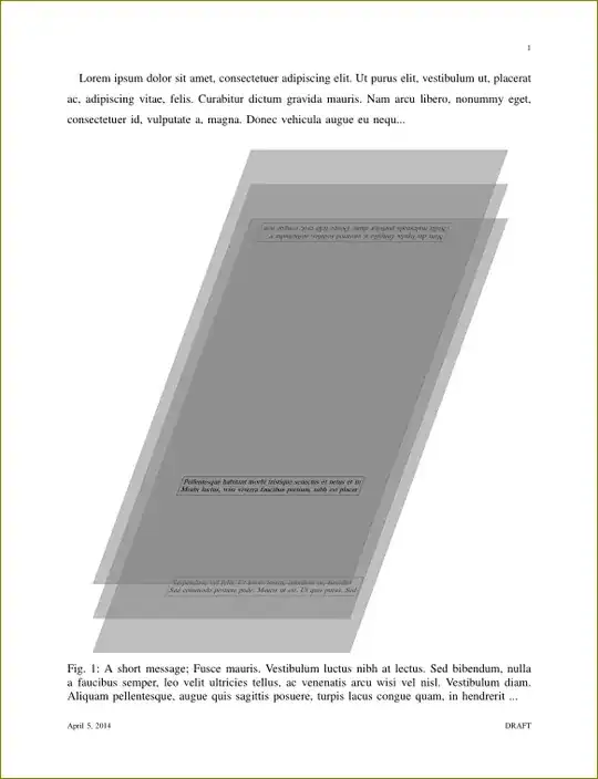
\captionof{figure}[short]{
A short message; \loremnchars[5]{255} ...
}
\label{fig:test}
\end{center}
\end{document}
When the lines marked %L1 and %L2 are commented, as in the MWE, I get the image in the page as expected (click for full-size):

Unfortunately, I have a bunch of nodes like %L1, laying outside the 3d scopes, which mess up the adjustbox margin calculation. So, since I need those nodes, I thought - maybe I can clip without removing those nodes. Unfortunately again, when I try doing that - by uncommenting the %L1 and %L2 lines in the MWE above - then I get a messed up clip, and the influence of the node is still visible:

So my question is - how can I clip the tikzpicture, so the node %L1 remains, and yet I still obtain the same margins & perspective as on the first screenshot?
pgfinterruptboundingboxbefore; thankfully I don't have any content in those nodes that I want to avoid, so this approach works for me ... cheers! – sdaau Apr 04 '14 at 23:53overlayoption to the node should do the same effect. – percusse Apr 05 '14 at 08:52