15

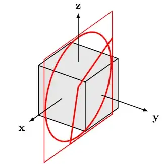
In the following code, I'm trying to draw three clipped circles in three orthogonal planes. I'm using this approach to clip the appropriate sections of the circles. This works nicely in the xy and yz planes, but not in the xz plane, as shown in the output.

enter image description here

Based on the output, it seems I have made a simple mistake, but I just can't find it. I've tried checking the coordinates in the scope for the xz plane (red circle), and they appear to be correct. I've attached three figures which show the clipping paths for each scope. (The drawn clipping paths show some minor inaccuracies, but these are irrelevant to the problem.) Any help finding the error would be much appreciated.

Some mathematical properties which might make the code clearer:

  • The center of the box is the point (1,1,1)
  • The drawn axes meet at (1,1,1), not the origin, so the figure is essentially shifted [1,1,1]
  • All the circles are concentric with center point (1,1,1)
  • The radius of the circles is 2

\documentclass[11pt]{standalone}
\usepackage[utf8]{inputenc}
\usepackage{tikz,tikz-3dplot}
    \usetikzlibrary{arrows}

\begin{document}

\definecolor{darkgreen}{rgb}{0.1,0.7,0.1}
\tdplotsetmaincoords{60}{125}

\begin{tikzpicture}[tdplot_main_coords,>=latex]

    \pgfsetlinewidth{0.8}

    \tdplotsetcoord{P}{3.4641}{54.74}{45}

    % box
    \draw[fill=black!10] (Px) -- (Pxy) -- (Py) -- (Pyz) -- (Pz) -- (Pxz) -- cycle;
    \draw (Pxy)  --  (P);
    \draw (Pxz)  --  (P);
    \draw (Pyz)  --  (P);

    \pgfsetlinewidth{1.4}

    \begin{scope} % blue circle, xy plane
        \color{blue}
        \tikzstyle{reverseclip}=[insert path={(3.1,3.1,1) -- (-1.1,3.1,1) -- (-1,-1.1,1) -- (3.1,-1.1,1) -- (3.1,3.1,1)}]
        \begin{pgfinterruptboundingbox}
            \path[clip] (1,1,1) -- (1.3,-1.1,1) -- (-1.1,-1.1,1) -- (-1.1,2,1) -- cycle [reverseclip];
        \end{pgfinterruptboundingbox}
        \pgfpathellipse{\pgfpointxyz{1}{1}{1}}{\pgfpointxyz{2}{0}{0}}{\pgfpointxyz{0}{2}{0}}
        \pgfusepath{draw}
    \end{scope}

    \begin{scope} % green circle, yz plane
        \color{darkgreen}
        \tikzstyle{reverseclip}=[insert path={(1,3.1,3.1) -- (1,3.1,-1.1) -- (1,-1.1,-1.1) -- (1,-1.1,3.1) -- (1,3.1,3.1)}]
        \begin{pgfinterruptboundingbox}
            \path[clip] (1,1,1) -- (1,-1.1,1.8) -- (1,-1.1,-1.1) -- (1,1.7,-1.1) -- cycle [reverseclip];
        \end{pgfinterruptboundingbox}
        \pgfpathellipse{\pgfpointxyz{1}{1}{1}}{\pgfpointxyz{0}{2}{0}}{\pgfpointxyz{0}{0}{2}}
        \pgfusepath{draw}
    \end{scope}

    \begin{scope} % red circle, xz plane
        \color{red}
        \tikzstyle{reverseclip}=[insert path={(3.1,1,3.1) -- (-1.1,1,3.1) -- (-1.1,1,-1.1) -- (3.1,1,-1.1) -- (3.1,1,3.1)}]
        \begin{pgfinterruptboundingbox}
            \path[clip] (1,1,1) -- (-1.1,1,2) -- (-1.1,1,-1.1) -- (1.5,1,-1.1) -- cycle [reverseclip];
        \end{pgfinterruptboundingbox}
        \pgfpathellipse{\pgfpointxyz{1}{1}{1}}{\pgfpointxyz{2}{0}{0}}{\pgfpointxyz{0}{0}{2}}
        \pgfusepath{draw}
    \end{scope}

    % axes
    \draw[line width=0.8pt,->]  (2,1,1)  --  (4,1,1)  node[anchor=north  east]{\textbf{x}};
    \draw[line width=0.8pt,->]  (1,2,1)  --  (1,4,1)  node[anchor=north  west]{\textbf{y}};
    \draw[line width=0.8pt,->]  (1,1,2)  --  (1,1,4)  node[anchor=south]{\textbf{z}};

\end{tikzpicture}

\end{document}

enter image description here enter image description here enter image description here

eiterorm
  • 1,813
  • 2
  • 15
  • 29
  • 1
    It's impressive how much work went into asking this question! – Charles Staats May 16 '14 at 16:57
  • @CharlesStaats, should I not try and solve my own problem before I ask here? I still can't seem to figure out what's wrong. Perhaps I'm blind. – eiterorm May 16 '14 at 22:34
  • 2
    @eiterorm: Of course you should. Its just that most people don't make that much of an effort to debug the problem - am sure I am guilty of that on occasion. So, it is great that you did. And in this case it is good to have such a question here, even if you had solved it. Self answers are perfectly acceptable. See: Is it proper to post a first attempt as a self-answer? and Should I self answer my question? – Peter Grill May 16 '14 at 23:57
  • When I compile your code, the bottom of the image is cut off. E.g. I don't see the bottom bit of the red circle show in your picture. – cfr May 17 '14 at 02:29
  • @cfr, it seems this is difference in behavior is caused by different versions of pgf. I found out I had an outdated version of pgf, so I updated it, and now I, too, get output with a cropped bottom. I don't know why. If anyone happens to read this and know the answer, please do leave a comment. – eiterorm May 17 '14 at 20:44
  • Somehow the clipping confuses standalone? – cfr May 17 '14 at 20:52
  • @cfr, it is pretty clear that the canvas is smaller than the actual picture. However, I thought the path and draw commands were supposed to increase the size of the canvas. They did before. – eiterorm May 17 '14 at 20:55
  • Yes, I thought so, too. Not a solution but if you put an invisible node at the bottom of the red/green circle, I'm guessing it will avoid cutting the bottom off. EDIT: e.g. \node at (2,0,-1) {}; works. – cfr May 17 '14 at 21:00
  • @cfr, actually, it turns out to be caused by the pgfinterruptboundingbox. Commenting out the box in the last scope makes the entire figure show. This also means that it's only the path command (not the draw command) which expands the canvas. – eiterorm May 17 '14 at 21:03
  • If I reduce the picture to just draw 3 axes (with \draw), it all fits. Even if I remove the nodes with anchors and labels so it is just \draw commands... – cfr May 17 '14 at 21:07
  • 1
    @cfr, very true! I should have said that the pgf command draw (on a previously defined path) doesn't seem to expand the canvas (because the expansion is caused by the path command). – eiterorm May 17 '14 at 21:11

2 Answers2

9

Use

\path[clip] (1.5,1,-1.1) -- (-1.1,1,-1.1) -- (-1.1,1,2) -- (1,1,1) -- cycle [reverseclip];

in the last case, reversing the direction of the clipping path.

Reverse the path...

\documentclass[11pt]{standalone}
\usepackage[utf8]{inputenc}
\usepackage{tikz,tikz-3dplot}
    \usetikzlibrary{arrows}

\begin{document}

\definecolor{darkgreen}{rgb}{0.1,0.7,0.1}
\tdplotsetmaincoords{60}{125}

\begin{tikzpicture}[tdplot_main_coords,>=latex]

    \pgfsetlinewidth{0.8}

    \tdplotsetcoord{P}{3.4641}{54.74}{45}

    % box
    \draw[fill=black!10] (Px) -- (Pxy) -- (Py) -- (Pyz) -- (Pz) -- (Pxz) -- cycle;
    \draw (Pxy)  --  (P);
    \draw (Pxz)  --  (P);
    \draw (Pyz)  --  (P);

    \pgfsetlinewidth{1.4}

    \begin{scope} % blue circle, xy plane
        \color{blue}
        \tikzstyle{reverseclip}=[insert path={(3.1,3.1,1) -- (-1.1,3.1,1) -- (-1,-1.1,1) -- (3.1,-1.1,1) -- (3.1,3.1,1)}]
        \begin{pgfinterruptboundingbox}
            \path[clip] (1,1,1) -- (1.3,-1.1,1) -- (-1.1,-1.1,1) -- (-1.1,2,1) -- cycle [reverseclip];
        \end{pgfinterruptboundingbox}
        \pgfpathellipse{\pgfpointxyz{1}{1}{1}}{\pgfpointxyz{2}{0}{0}}{\pgfpointxyz{0}{2}{0}}
        \pgfusepath{draw}
    \end{scope}

    \begin{scope} % green circle, yz plane
        \color{darkgreen}
        \tikzstyle{reverseclip}=[insert path={(1,3.1,3.1) -- (1,3.1,-1.1) -- (1,-1.1,-1.1) -- (1,-1.1,3.1) -- (1,3.1,3.1)}]
        \begin{pgfinterruptboundingbox}
            \path[clip] (1,1,1) -- (1,-1.1,1.8) -- (1,-1.1,-1.1) -- (1,1.7,-1.1) -- cycle [reverseclip];
        \end{pgfinterruptboundingbox}
        \pgfpathellipse{\pgfpointxyz{1}{1}{1}}{\pgfpointxyz{0}{2}{0}}{\pgfpointxyz{0}{0}{2}}
        \pgfusepath{draw}
    \end{scope}

    \begin{scope} % red circle, xz plane
        \color{red}
        \tikzstyle{reverseclip}=[insert path={(3.1,1,3.1) -- (-1.1,1,3.1) -- (-1.1,1,-1.1) -- (3.1,1,-1.1) -- (3.1,1,3.1)}]
        \begin{pgfinterruptboundingbox}
             \path[clip] (1.5,1,-1.1) -- (-1.1,1,-1.1) -- (-1.1,1,2) -- (1,1,1) -- cycle [reverseclip];
        \end{pgfinterruptboundingbox}
        \pgfpathellipse{\pgfpointxyz{1}{1}{1}}{\pgfpointxyz{2}{0}{0}}{\pgfpointxyz{0}{0}{2}}
        \pgfusepath{draw}
    \end{scope}

    % axes
    \draw[line width=0.8pt,->]  (2,1,1)  --  (4,1,1)  node[anchor=north  east]{\textbf{x}};
    \draw[line width=0.8pt,->]  (1,2,1)  --  (1,4,1)  node[anchor=north  west]{\textbf{y}};
    \draw[line width=0.8pt,->]  (1,1,2)  --  (1,1,4)  node[anchor=south]{\textbf{z}};

\end{tikzpicture}

\end{document}

This gave me the idea:

Idea

\documentclass[11pt,crop=false,preview=false]{standalone}
\usepackage[utf8]{inputenc}
\usepackage{tikz,tikz-3dplot}
    \usetikzlibrary{arrows}

\begin{document}

\definecolor{darkgreen}{rgb}{0.1,0.7,0.1}
\tdplotsetmaincoords{60}{125}

\begin{tikzpicture}[tdplot_main_coords,>=latex]

    \pgfsetlinewidth{0.8}

    \tdplotsetcoord{P}{3.4641}{54.74}{45}

    % box
    \draw[fill=black!10] (Px) -- (Pxy) -- (Py) -- (Pyz) -- (Pz) -- (Pxz) -- cycle;
    \draw (Pxy)  --  (P);
    \draw (Pxz)  --  (P);
    \draw (Pyz)  --  (P);

    \pgfsetlinewidth{1.4}

    \begin{scope} % blue circle, xy plane
        \color{blue}
        \tikzstyle{reverseclip}=[insert path={(3.1,3.1,1) -- (-1.1,3.1,1) -- (-1,-1.1,1) -- (3.1,-1.1,1) -- (3.1,3.1,1)}]
        \begin{pgfinterruptboundingbox}
            \path[clip] (1,1,1) -- (1.3,-1.1,1) -- (-1.1,-1.1,1) -- (-1.1,2,1) -- cycle [reverseclip];
        \end{pgfinterruptboundingbox}
        \pgfpathellipse{\pgfpointxyz{1}{1}{1}}{\pgfpointxyz{2}{0}{0}}{\pgfpointxyz{0}{2}{0}}
        \pgfusepath{draw}
    \end{scope}

    \begin{scope} % green circle, yz plane
        \color{darkgreen}
        \tikzstyle{reverseclip}=[insert path={(1,3.1,3.1) -- (1,3.1,-1.1) -- (1,-1.1,-1.1) -- (1,-1.1,3.1) -- (1,3.1,3.1)}]
        \begin{pgfinterruptboundingbox}
           \draw[purple,->] (1,1,1) -- (1,-1.1,1.8) -- (1,-1.1,-1.1) -- (1,1.7,-1.1);
           \path[clip] (1,1,1) -- (1,-1.1,1.8) -- (1,-1.1,-1.1) -- (1,1.7,-1.1) -- cycle [reverseclip];
        \end{pgfinterruptboundingbox}
        \pgfpathellipse{\pgfpointxyz{1}{1}{1}}{\pgfpointxyz{0}{2}{0}}{\pgfpointxyz{0}{0}{2}}
        \pgfusepath{draw}
    \end{scope}

    \begin{scope} % red circle, xz plane
        \color{red}
        \tikzstyle{reverseclip}=[insert path={(3.1,1,3.1) -- (-1.1,1,3.1) -- (-1.1,1,-1.1) -- (3.1,1,-1.1) -- (3.1,1,3.1)}]
        \begin{pgfinterruptboundingbox}
            \draw[orange,->] (1,1,1) -- (-1.1,1,2) -- (-1.1,1,-1.1) -- (1.5,1,-1.1);
            \path[clip] (1,1,1) -- (-1.1,1,2) -- (-1.1,1,-1.1) -- (1.5,1,-1.1) -- cycle [reverseclip];
        \end{pgfinterruptboundingbox}
        \pgfpathellipse{\pgfpointxyz{1}{1}{1}}{\pgfpointxyz{2}{0}{0}}{\pgfpointxyz{0}{0}{2}}
        \pgfusepath{draw}
    \end{scope}

    % axes
    \draw[line width=0.8pt,->]  (2,1,1)  --  (4,1,1)  node[anchor=north  east]{\textbf{x}};
    \draw[line width=0.8pt,->]  (1,2,1)  --  (1,4,1)  node[anchor=north  west]{\textbf{y}};
    \draw[line width=0.8pt,->]  (1,1,2)  --  (1,1,4)  node[anchor=south]{\textbf{z}};

\end{tikzpicture}

\end{document}
cfr
  • 198,882
  • Thanks! I didn't realize the direction of the path was essential to the result. – eiterorm May 17 '14 at 20:45
  • @eiterorm I don't realise anything if it is tikz but I'm trying to learn and sometimes playing helps. I just noticed the paths went in opposite directions and thought maybe, possibly... (Very unscientific explanation, too, since the paths are in different planes so it is not at all obvious what 'opposite' means.) – cfr May 17 '14 at 20:48
  • 1
    if I were to guess, I'd say it is related to the direction of the path of the outer path (named 'reverseclip' in this example). I haven't investigated this, though. – eiterorm May 17 '14 at 20:53
6

Perhaps in this case you can get away using arcs and the rotate around keys which rotate the coordinate system around the specified axis vector as shown below (note, a shift is to the center of the box is needed for this to wrk). It does, however, require the latest version of PGF. I have taken some liberties with the original code.

\documentclass[tikz,border=5]{standalone}
\usepackage{tikz-3dplot}
\begin{document}

\definecolor{dark green}{rgb}{0.1,0.7,0.1}
\tdplotsetmaincoords{60}{125}

\begin{tikzpicture}[tdplot_main_coords,>=latex, thick, line cap=round, line join=round]

\tdplotsetcoord{P}{3.4641}{54.74}{45}
\coordinate (O) at (1,1,1);
% box
\draw[fill=black!10] (Px) -- (Pxy) -- (Py) -- (Pyz) -- (Pz) -- (Pxz) -- cycle;
\draw (Pxy) --  (P) (Pxz) --  (P) (Pyz) --  (P);

\tikzset{shift={(O)}, ultra thick}

\draw  [blue, rotate around z=-90] 
  (15:2) arc (15:245:2);
\draw  [dark green, rotate around z=-90, rotate around x=90] 
  (15:2) arc (15:245:2);
\draw  [red, rotate around z=-90, rotate around y=90] 
  (15:2) arc (15:245:2);

\tikzset{thick}
% axes
\draw [->] (1,0,0) -- (3,0,0) node[below left]  {\textbf{x}};
\draw [->] (0,1,0) -- (0,3,0) node[below right] {\textbf{y}};
\draw [->] (0,0,1) -- (0,0,3) node[above]       {\textbf{z}};

\end{tikzpicture}

\end{document}

enter image description here

Mark Wibrow
  • 70,437
  • Thanks for the answer. While it doesn't solve the actual problem with the reversed clipping, it shows a great, different way to draw the same figure. – eiterorm May 17 '14 at 20:49