You can apply the same rotation to the centers of the non-rotated rectangle. In other words, the center of the non-rotated rectangles would be (3.1,-2.5). Hence the centers of the rotated rectangles are:
([rotate around={26.5:(3.1,-5)}]3.1,-2.5)
and
([rotate around={-26.5:(3.1,-5)}]3.1,-2.5)
Connecting these points yields:

I have just drawn a line, but that should let you draw any desired rectangle based on those coordinates.
Notes:
- One of drawbacks of this solution is that you need to specify the rotation values twice. Hence, using
\coordinates (as per Harish Kumar's solution) or \nodes (as per Ignasi's solution) isbetter.
Code:
\documentclass{article}
\usepackage{tikz}
\begin{document}
\begin{tikzpicture}
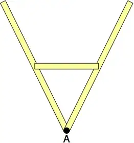
\draw[thick] (0,0) -- (6,0);
\draw[thick,fill=yellow!40, rotate around={26.5:(3.1,-5)} ] (3,0) rectangle (3.2,-5) node (a) {};
\draw[thick,fill=yellow!40, rotate around={-26.5:(3.1,-5)}] (3,0) rectangle (3.2,-5) node (b) {};
\draw[fill=black] (3.1,-5) circle(0.11);
\node at (3.1,-5.3) {A};
\draw [red, ultra thick]
([rotate around={26.5:(3.1,-5)}]3.1,-2.5) --
([rotate around={-26.5:(3.1,-5)}]3.1,-2.5);
\end{tikzpicture}
\end{document}


\documentclassand the appropriate packages so that those trying to help don't have to recreate it. – Peter Grill Nov 14 '14 at 01:40