In this answer, Jake points out
The
miteroption is more "correct" in that it doesn't add new corners to a shape or introduce rounding. In some cases with very sharp angles, the results might be undesirable though, as in the question you linked to...
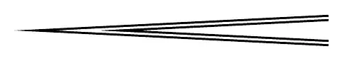
in reference to this question. It's certainly true that for very acute angles, a mitered joint will extend far beyond the coordinate where the two lines intersect. In some sense, this is because TikZ draws lines centered on the specified coordinates, which is almost always the desired result. But in this circumstance, it might be better to specify the outermost point of the miter as the "endpoint" of the lines, and have the strokes be entirely uncentered and to one side of the coordinates or the other. Illustrator (for example, because I have it handy) supports this, but only for closed paths, where there is a well-defined "inside" and "outside" to the path. For an acute angle, you could reuse "inside" or "outside" in a semi-sensical way, but that terminology may not generalize to single lines... For lack of better terminology then, I'll reuse "above" or "below" or "left" or "right", as are used to describe label positioning.
Is there a convenient way in TikZ to specify lines as being drawn "above" or "below" their coordinates---effectively being offset by exactly half the line-thickness in the direction perpendicular to the line? And is there a similar solution for drawing curves "above" or "below" their coordinates (not as easy to say "perpendicular to the line", though still mathematically possible)? If there isn't a good solution for arbitrary open paths, is there a good one for closed paths, as in Illustrator?
EDIT: To answer Andrew's question, Illustrator draws the following path by default, "inside" and "outside":

The top path is selected, which is drawn in blue highlighting. That stroke is "default", or centered. The middle is "inside", and draws the two subregions separately. The bottom is "outside". Here's a twistier, more self-intersecting example, that shows Illustrator has a miter limit, as well as an algorithm that seems to be parity-based:

Note that Illustrator limits "inside" and "outside" to solid strokes on closed paths only: if you attempt a dashed stroke, or have a non-closed path, or try tiger-striping like in Andrew's example, it disables the inside and outside options, which makes me wonder whether there happens to be a convenient PDF or PS command for offsetting simple strokes on simple paths, rather than a more robust solution...
I completely agree that the choice of side is not local, but on the other hand if you pick a single option for the first segment of the path (e.g., "to the right side, when headed from the first point on the path to the second"), it will stay consistent for the rest of the path.
The original question that prompted mine was the attempt to draw a cube in 3d with thickened edges. I was curious whether you could draw said cube by saying, "Draw the front face, stroked inside. Draw the (foreshortened) top face, stroked inside. Draw the (foreshortened) side face, stroked inside." In that scenario, Andrew's twisty paths don't come up and there still is a well-defined inside and outside, and the goal would be to have pointy corners as befits a cube, so the mitering would need to be specified by the outermost points...
EDIT: To follow-up on my commented question to Andrew's answer, here's what TikZ makes of his solution as applied to the figure-eight example he gave. The paths here are drawn in a figure-eight, starting in the direction of the arrow. They use the reverseclip style from this answer, and the exact path used is drawn in color over the clipped versions:

The red example uses clipping, and gets the "inside" to match Illustrator's behavior...but the blue example uses reverse clipping, and gets confused in the right half of the image. If I draw the figure-eights in the other orientation, then the red example stays the same, but the blue example gets confused on the left half of the image. And finally, the exact same styles, but using the "twisty" path I had above:
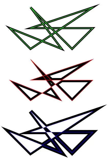
Both the red and blue paths are slightly confused, and while they don't follow Illustrator's even-odd algorithm, I have no idea what algorithm the are following...
(And finally, the TikZ code for the twisty paths I used, for anyone who wants to reproduce the behavior I'm seeing:
\documentclass{article}
%\url{https://tex.stackexchange.com/q/29991/86}
\usepackage{tikz}

\begin{document}
\begin{tikzpicture}[remember picture,overlay,scale=2,line width=2mm]
\tikzstyle{reverseclip}=[insert path={(current page.north east) --
  (current page.south east) --
  (current page.south west) --
  (current page.north west) --
  (current page.north east)}
]
\draw (0,1) -- (1,0) -- (4,2) -- (1,1) -- (4,1) -- (3,0) -- (1,2) -- (2.5,0) -- cycle;
\draw[green,line width=1pt] (0,1) -- (1,0) -- (4,2) -- (1,1) -- (4,1) -- (3,0) -- (1,2) -- (2.5,0) -- cycle;
\begin{scope}[yshift=-2.5cm,line width=4mm]
\begin{scope}
\clip (0,1) -- (1,0) -- (4,2) -- (1,1) -- (4,1) -- (3,0) -- (1,2) -- (2.5,0) -- cycle;
\draw (0,1) -- (1,0) -- (4,2) -- (1,1) -- (4,1) -- (3,0) -- (1,2) -- (2.5,0) -- cycle;
\end{scope}
\draw[red,line width=1pt] (0,1) -- (1,0) -- (4,2) -- (1,1) -- (4,1) -- (3,0) -- (1,2) -- (2.5,0) -- cycle;
\end{scope}
\begin{scope}[yshift=-5cm,line width=4mm]
\begin{pgfinterruptboundingbox}
\path[clip] (0,1) -- (1,0) -- (4,2) -- (1,1) -- (4,1) -- (3,0) -- (1,2) -- (2.5,0) -- cycle [reverseclip];
\draw (0,1) -- (1,0) -- (4,2) -- (1,1) -- (4,1) -- (3,0) -- (1,2) -- (2.5,0) -- cycle;
\end{pgfinterruptboundingbox}
\draw[blue,line width=1pt] (0,1) -- (1,0) -- (4,2) -- (1,1) -- (4,1) -- (3,0) -- (1,2) -- (2.5,0) -- cycle;
\end{scope}
\end{tikzpicture}
\end{document}


mitertobeveljoins if the angle between two line segments is too small, to prevent the line from extending too far past the specified coordinates. The threshold can be adjusted usingmiter limit=<number>. – Jake Sep 30 '11 at 04:01