One quite flexible option, which works for any custom "shape", is to define "pic" for your arrow. You can read all about these in section 18.2 of the tikz manual (version 3.0.1a).

This is done with essentially your code thrown inside a pic called myarrow that takes two arguments: the left and right colour. Here is the code:
\documentclass{beamer}
\beamertemplatenavigationsymbolsempty
\usepackage{tikz}
\usepackage{pgfplots}
\usetikzlibrary{arrows, arrows.meta}
\begin{document}
\tikzset{
pics/myarrow/.style args = {#1,#2}{% left colour, right colour
code={
\filldraw[left color=#1, right color=#2]
(0,0)--++(90:0.1)--++(0:1.)--++(90:0.1)--++(-45:.212)
--++(-135:.212)--++(90:0.1)--cycle;
}
}
}
\begin{frame}[fragile,t]
\frametitle{}
\begin{tikzpicture}[scale=.9, transform shape]
\draw [thick,-latex](0,0) -- (4,0);
\draw [thick,-latex](0,0) -- (0,2.);
\draw [ultra thick, green, -latex'] (.2,.8) -- +(0:.76);
\draw [ultra thick, red, -latex'] (.4,.5) -- +(0:.76);
\draw [ultra thick, violet, -latex'] (.6,.2) -- +(0:.76);
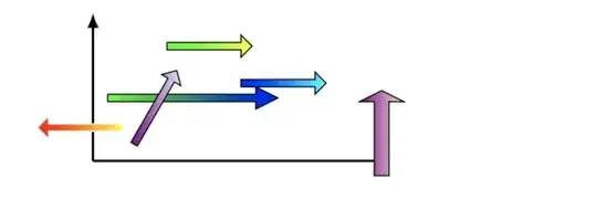
\pic at (2,1) {myarrow={blue,cyan}};
\draw (1,2) pic{myarrow={green,yellow}};
\end{tikzpicture}
\end{frame}
\end{document}
The coordinates inside myarrow are relative to where you place the arrow. As shown above, you can place the pic using either a \draw command or a \pic command.
Edit
You can add extra augments to the definition of the pic to change the length etc. Of course, if you want to be able to change the length, the angle, the ... then you will end up adding many additional arguments and this soon becomes a little cumbersome. Another approach is to define some pgfkeys to control the additional specifications using a more manageable key-value syntax; this is done, for example, in this post How can I create a parent node in tikz with parts of the node designated for pointers?.
In this case, I think that the best approach is to add a third argument and have the pic use a scope environment that is controlled by #3. This allows you to produce:

using the code:
\documentclass{beamer}
\beamertemplatenavigationsymbolsempty
\usepackage{tikz}
\usepackage{pgfplots}
\usetikzlibrary{arrows, arrows.meta}
\begin{document}

\tikzset{
  pics/myarrow/.style args = {#1,#2,#3}{% left colour, right colour
    code={
      \begin{scope}[#3]
        \filldraw[left color=#1, right color=#2]
           (0,0)--++(90:0.1)--++(0:1.)--++(90:0.1)--++(-45:.212)
                --++(-135:.212)--++(90:0.1)--cycle;
      \end{scope}
    }
  }
}

\begin{frame}[fragile,t]
  \frametitle{}
  \begin{tikzpicture}[scale=.9, transform shape]
    \draw [thick,-latex](0,0) -- (4,0);
    \draw [thick,-latex](0,0) -- (0,2.);
    \draw (1,1.5) pic{myarrow={green,yellow,}};
    \pic at (2,1) {myarrow={blue,cyan,}};
    \pic at (.2,.8) {myarrow={green,blue,xscale=2}};
    \pic at (.4,.5) {myarrow={red,yellow,scale=-1}};
    \pic at (.6,.2) {myarrow={violet,blue!10!white,rotate=60}};
    \pic at (4,-.2){myarrow={violet,red!10!white,{rotate=90,yscale=2}}};
  \end{tikzpicture}
\end{frame}
\end{document}
One thing to be careful of here is that pics are very unforgiving if you don't use their syntax exactly as specified: above, you always need to give myarrrow three comma separated arguments. Hence, the trailing comma in myarrow={blue,cyan,}, which sets #3 to be nothing in the second example above, and the braces around the third augment rotate=90,yscale=2 in the last example myarrow={violet,red!10!white,{rotate=90,yscale=2}}}. In fact, you can abuse this and, for example, use
\pic at (.4,.5) {myarrow={{red,draw=white},yellow,scale=-1}};
to add optional augments to the \filldraw command in myarrow, which in this case changes the boarder of the arrow from black to white. This changes the last image above to:
Note that the arrow pointing from right to left has a white boarder.


