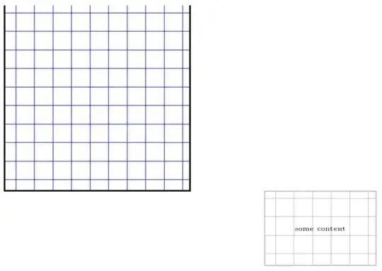
From your comments I understand that you want a grid that moves with the node or some other path. This can be easily obtained with a path picture.
\documentclass[tikz,border=3.14mm]{standalone}
\usetikzlibrary{calc}
\pgfkeys{/Zarko/.cd,
grid/.style={draw=gray!50,thin},
x distance/.initial=8mm,
y distance/.initial=8mm,
distance/.code={\pgfkeys{/Zarko/x distance=#1,/Zarko/y distance=#1}}
}
\tikzset{Zarko grid/.style={/utils/exec=\pgfkeys{/Zarko/.cd,#1},
path picture={
\path[/Zarko/grid] let \p1=($(path picture bounding box.north east)-(path picture bounding
box.south west)$),\n1={int(\x1/\pgfkeysvalueof{/Zarko/x distance})},
\n2={int(\y1/\pgfkeysvalueof{/Zarko/y distance})} in
foreach \XX in {1,...,\n1}
{
([xshift=\XX*\pgfkeysvalueof{/Zarko/x distance}]path picture bounding box.south west)
--
([xshift=\XX*\pgfkeysvalueof{/Zarko/x distance}]path picture bounding box.north west)
}
foreach \YY in {1,...,\n2} {
([yshift=\YY*\pgfkeysvalueof{/Zarko/y distance}]path picture bounding box.south west)
--
([yshift=\YY*\pgfkeysvalueof{/Zarko/y distance}]path picture bounding box.south east)
};
}}}
\begin{document}
    \begin{tikzpicture}
\node (s)   [Zarko grid,draw=gray!50, thick,
             minimum width=30mm, minimum height=20mm]  {some content};

\node (s')   [Zarko grid={distance=3mm},draw=gray!50, thick,
             minimum width=30mm, minimum height=24mm]  at (0,-4) {some content};
\draw[blue,Zarko grid={x distance=4mm,y distance=2mm,grid/.style={draw=red}}] (4,0) --(6,3) -- (5,-2) -- cycle;
\end{tikzpicture}
\end{document}

One could make it more flexible by adding some x offset and y offset but I guess you will be able to do that when needed.
As for "honest-to-god" grids: I copied my old answer and it seems to work. (I only had to add the color to the options of the grid, no idea why I didn't do that in the original answer.) EDIT: I cleaned my code, when I wrote the answer I didn't know, for instance, that the calc package (not library) redefines \setlength etc. So I hope to have made my code a bit less dangerous.
\documentclass[tikz,border=3.14mm]{standalone}
\usetikzlibrary{patterns}
\makeatletter
\newlength{\flex@pattern@density}
\newlength{\flex@pattern@linewidth}
\newlength{\flex@pattern@auxlength}
\newlength{\flex@pattern@auxlengthtwo}
\tikzset{/tikz/.cd,
    pattern density/.code={\flex@pattern@density=#1
    \flex@pattern@auxlength=1.1\flex@pattern@density
    \flex@pattern@auxlengthtwo=\flex@pattern@density
    \advance\flex@pattern@auxlengthtwo by 0.1pt
    %\typeout{\the\flex@pattern@density,\the\flex@pattern@auxlength}
    },
    pattern density=3pt,
    pattern line width/.code={\flex@pattern@linewidth=#1},
    pattern line width=0.4pt,
}


\pgfdeclarepatternformonly[\flex@pattern@density,\flex@pattern@linewidth,\tikz@pattern@color]{flexible horizontal lines}{\pgfpointorigin}{\pgfqpoint{100pt}{1pt}}{\pgfqpoint{100pt}{\flex@pattern@density}}%
{
  \pgfsetlinewidth{\flex@pattern@linewidth}
  \pgfsetcolor{\tikz@pattern@color}
  \pgfpathmoveto{\pgfqpoint{0pt}{0.5pt}}
  \pgfpathlineto{\pgfqpoint{100pt}{0.5pt}}
  \pgfusepath{stroke}
}

\pgfdeclarepatternformonly[\flex@pattern@density,\flex@pattern@linewidth,\tikz@pattern@color]{flexible vertical lines}{\pgfpointorigin}{\pgfqpoint{1pt}{100pt}}{\pgfqpoint{\flex@pattern@density}{100pt}}%
{
  \pgfsetlinewidth{\flex@pattern@linewidth}
  \pgfsetcolor{\tikz@pattern@color}
  \pgfpathmoveto{\pgfqpoint{0.5pt}{0pt}}
  \pgfpathlineto{\pgfqpoint{0.5pt}{100pt}}
  \pgfusepath{stroke}
}

\pgfdeclarepatternformonly[\flex@pattern@auxlengthtwo,\flex@pattern@density,\flex@pattern@linewidth,\flex@pattern@auxlength,\tikz@pattern@color]{flexible north east lines}{\pgfqpoint{-1pt}{-1pt}}{\pgfqpoint{\flex@pattern@auxlength}{\flex@pattern@auxlength}}{\pgfqpoint{\flex@pattern@density}{\flex@pattern@density}}%
{
  \pgfsetlinewidth{\flex@pattern@linewidth}
  \pgfsetcolor{\tikz@pattern@color}
  \pgfpathmoveto{\pgfqpoint{0pt}{0pt}}
  \pgfpathlineto{\pgfqpoint{\flex@pattern@auxlengthtwo}{\flex@pattern@auxlengthtwo}}
  \pgfusepath{stroke}
}

\pgfdeclarepatternformonly[\flex@pattern@auxlengthtwo,\flex@pattern@density,\flex@pattern@linewidth,\flex@pattern@auxlength,\tikz@pattern@color]{flexible north west lines}{\pgfqpoint{-1pt}{-1pt}}{\pgfqpoint{\flex@pattern@auxlength}{\flex@pattern@auxlength}}{\pgfqpoint{\flex@pattern@density}{\flex@pattern@density}}%
{
  \pgfsetlinewidth{\flex@pattern@linewidth}
  \pgfsetcolor{\tikz@pattern@color}
  \pgfpathmoveto{\pgfqpoint{\flex@pattern@auxlengthtwo}{0pt}}
  \pgfpathlineto{\pgfqpoint{0pt}{\flex@pattern@auxlengthtwo}}
  \pgfusepath{stroke}
}


% Crossed lines in different directions

\pgfdeclarepatternformonly[\flex@pattern@density,\flex@pattern@linewidth,\flex@pattern@auxlength,\tikz@pattern@color]{flexible grid}{\pgfqpoint{-1pt}{-1pt}}{\pgfqpoint{\flex@pattern@auxlength}{\flex@pattern@auxlength}}{\pgfqpoint{\flex@pattern@density}{\flex@pattern@density}}%
{
  \pgfsetlinewidth{\flex@pattern@linewidth}
  \pgfsetcolor{\tikz@pattern@color}
  \pgfpathmoveto{\pgfqpoint{0pt}{0pt}}
  \pgfpathlineto{\pgfqpoint{0pt}{\flex@pattern@density}}
  \pgfpathmoveto{\pgfqpoint{0pt}{0pt}}
  \pgfpathlineto{\pgfqpoint{\flex@pattern@density}{0pt}}
  \pgfusepath{stroke}
}

\pgfdeclarepatternformonly[\flex@pattern@density,\flex@pattern@linewidth,\flex@pattern@auxlength,\tikz@pattern@color]{flexible crosshatch}{\pgfqpoint{-1pt}{-1pt}}{\pgfqpoint{\flex@pattern@auxlength}{\flex@pattern@auxlength}}{\pgfqpoint{3pt}{3pt}}%
{
  \pgfsetlinewidth{\flex@pattern@linewidth}
  \pgfsetcolor{\tikz@pattern@color}
  \pgfpathmoveto{\pgfqpoint{\flex@pattern@density}{0pt}}
  \pgfpathlineto{\pgfqpoint{0pt}{\flex@pattern@density}}
  \pgfpathmoveto{\pgfqpoint{0pt}{0pt}}
  \pgfpathlineto{\pgfqpoint{\flex@pattern@density}{\flex@pattern@density}}
  \pgfusepath{stroke}
}


% Dotted regions

\pgfdeclarepatternformonly[\flex@pattern@density,\flex@pattern@linewidth,\tikz@pattern@color]{flexible dots}{\pgfqpoint{-1pt}{-1pt}}{\pgfqpoint{1pt}{1pt}}{\pgfqpoint{\flex@pattern@density}{\flex@pattern@density}}%
{
  \pgfsetcolor{\tikz@pattern@color}
  \pgfpathcircle{\pgfqpoint{0pt}{0pt}}{\flex@pattern@linewidth}
  \pgfusepath{fill}
}

\pgfdeclarepatternformonly[\flex@pattern@density,\flex@pattern@linewidth,\tikz@pattern@color]{flexible crosshatch dots}{\pgfqpoint{-1pt}{-1pt}}{\pgfqpoint{2.5pt}{2.5pt}}{\pgfqpoint{\flex@pattern@density}{\flex@pattern@density}}%
{
  \pgfsetcolor{\tikz@pattern@color}
  \pgfpathcircle{\pgfqpoint{0pt}{0pt}}{\flex@pattern@linewidth}
  \pgfpathcircle{\pgfqpoint{1.5pt}{1.5pt}}{\flex@pattern@linewidth}
  \pgfusepath{fill}
}

\makeatother


\begin{document}
 \begin{tikzpicture}[>=stealth,every node/.style={font=\tiny}]
  \draw[very thick,
   pattern=flexible grid,pattern line
   width=0.4pt,pattern color=blue,
   pattern density=5mm] (0,5) -- (0,0) -- (5,0) -- (5,5);
  \begin{scope}[pattern density=5mm,pattern line
   width=0.4pt]
    \node (s)  [draw=gray!50, thick,pattern color=gray!50,
             preaction={pattern=flexible grid},
             minimum width=30mm, minimum height=20mm,
             below right] at (7,0)  {some content};
  \end{scope}
 \end{tikzpicture}

\end{document}
ADDENDUM: If I use the same preamble for
\begin{document}
\foreach \X in {2,2.033,...,4,3.967,...,2}
{\begin{tikzpicture}[>=stealth,every node/.style={font=\tiny}]
  \draw (0,-3) rectangle (8,5);
  \begin{scope}[pattern density=5mm,pattern line
   width=0.4pt]
    \node (s)  [draw=gray!50, thick,pattern color=gray!50,
             preaction={pattern=flexible grid},
             minimum width=30mm, minimum height=20mm,
             below right] at (\X,{sin(\X*90)})  {some content};
    \node (s')  [draw=gray!50, thick,pattern color=gray!50,
             preaction={pattern=grid},
             minimum width=30mm, minimum height=20mm,
             below right] at (\X,{3+sin(\X*90)})  {some content};
  \end{scope}
\end{tikzpicture}}
\end{document}
I get this "beautiful" animation:

It shows that the patterns are, in principle, equally in hitting the boundary of the node, it is only that the finer pattern has statistically a better chance of doing so, but other than that the patterns are on the same footing.


Zarko grid={...}. for example, i like to add grid color (change default choice here) and thickness of lines (also possible change default value). – Zarko Feb 11 '19 at 10:16\draw[blue,Zarko grid={x distance=4mm,y distance=2mm,grid/.style={draw=red}}] (4,0) --(6,3) -- (5,-2) -- cycle;You can add your thickness togrid/.style. – Feb 11 '19 at 14:40