This adds a style that uses a graphic for the connection bars. The usage is
use image for connecting bar=<graphics>
Please note that this requires you to set the concept color for the children,
every child/.style={concept color=<color>},
where the color is used for the halo.
\documentclass[margin=10pt]{standalone}
\usepackage[dvipsnames,svgnames]{xcolor}
\usepackage{tikz}
\usetikzlibrary{mindmap,shadows}
\usepackage{fontspec}
\tikzset{node background pic/.style 2 args={
          fill=none,draw,
          path picture={\node[every node/.style={}] at (path picture bounding box.center)
              {\includegraphics[width=#1,height=#1]{#2}};},%},
          },golden/.style={node background pic={#1}{GoldLeaf.jpg}},
          golden/.default=4cm}
\makeatletter
\tikzset{use image for connecting bar/.code={\def\tikz@lib@shade@pic{%
  % We have to draw the shading...
  % compute start point:
 \pgftransformreset%
 % compute the distance
 \pgfpointdiff{\pgfpointanchor{\tikz@lib@save@start}{center}}{\pgfpointanchor{\tikz@lib@save@target}{center}}%
 \pgfmathsetmacro\pgfutil@tempa{1+10*sqrt(0.01*\pgf@x*\pgf@x+0.01*\pgf@y*\pgf@y)%
 -\tikz@lib@saved@start@radius-\tikz@lib@saved@end@radius}
 %
 \pgf@process{\pgfpointnormalised{\pgfpointdiff{\pgfpointanchor{\tikz@lib@save@start}{center}}{\pgfpointanchor{\tikz@lib@save@target}{center}}}}%
  \edef\tikz@lib@mm@vec{\noexpand\pgfqpoint{\the\pgf@x}{\the\pgf@y}}%
  \pgfmathsetlength\pgf@xc{\tikz@lib@saved@start@radius}
  \pgf@process{\pgfpointadd{\pgfpointtransformed{\pgfpointanchor{\tikz@lib@save@start}{center}}}
                           {\pgfpointscale{\pgf@sys@tonumber{\pgf@xc}}{\tikz@lib@mm@vec}}}
  \edef\tikz@lib@mm@start{\noexpand\pgfqpoint{\the\pgf@x}{\the\pgf@y}}%
  \pgfmathsetlength\pgf@xc{\tikz@lib@saved@end@radius}
  \pgf@process{\pgfpointdiff{\tikz@lib@mm@start}{\pgfpointadd{\pgfpointtransformed{\pgfpointanchor{\tikz@lib@save@target}{center}}}
                           {\pgfpointscale{-\pgf@sys@tonumber{\pgf@xc}}{\tikz@lib@mm@vec}}}}
  \edef\tikz@lib@mm@end{\noexpand\pgfqpoint{\the\pgf@x}{\the\pgf@y}}%
  \pgftransformshift{\tikz@lib@mm@start}
   \pgflowlevelsynccm
  \pgf@process{\tikz@lib@mm@vec}
  {
    \pgf@xa=-\pgf@x%
    \pgftransformcm{\pgf@sys@tonumber{\pgf@x}}{\pgf@sys@tonumber{\pgf@y}}%
      {\pgf@sys@tonumber{\pgf@y}}{\pgf@sys@tonumber{\pgf@xa}}%
      {\pgfpointorigin}%
    \pgf@process{\pgfpointtransformed{\tikz@lib@mm@end}}%
    \expandafter
  }
  \edef\tikz@lib@mm@length{\the\pgf@x}%
  \pgf@process{\tikz@lib@mm@vec}
  \pgf@ya=-\pgf@y%
  \pgftransformcm{\pgf@sys@tonumber{\pgf@x}}{\pgf@sys@tonumber{\pgf@y}}%
    {\pgf@sys@tonumber{\pgf@ya}}{\pgf@sys@tonumber{\pgf@x}}%
    {\pgfpointorigin}%
  % Y scale:
  \pgfmathsetlength\pgf@y{\tikz@lib@saved@start@radius}%
  \pgfmathsetlength\pgf@ya{\tikz@lib@saved@end@radius}%
  \ifdim\pgf@y<\pgf@ya%
    \pgf@y=\pgf@ya%
  \fi%
  \pgf@y=0.01992528\pgf@y%
  \pgftransformyscale{\pgf@sys@tonumber{\pgf@y}}%
  \pgfpathrectanglecorners
  {\pgfpoint{-\tikz@lib@saved@start@radius}{-50bp}}
  {\pgfpoint{1pt}{50bp}}
  \pgfsetfillcolor{tikz@switch@from}
  \pgfusepath{fill}
  \pgfpathrectanglecorners
  {\pgfpoint{\tikz@lib@mm@length+\tikz@lib@saved@end@radius}{-50bp}}
  {\pgfpoint{\tikz@lib@mm@length-1pt}{50bp}}
  \pgfsetfillcolor{tikz@switch@to}
  \pgfusepath{fill}
  % X scale:
  \pgf@x=\tikz@lib@mm@length%
  \pgf@x=0.009962\pgf@x%
  \pgftransformxscale{\pgf@sys@tonumber{\pgf@x}}%
  \pgftransformxshift{50bp}
  \pgflowlevelsynccm%
  %\pgfuseshading{tikz@shade@bar}%<removed and the following is added
  \pgfnode{rectangle}{center}{\includegraphics[width=\pgfutil@tempa pt]{#1}}{}{}%
}}}%
\makeatother
\begin{document}
    \begin{tikzpicture}[mindmap,
      font=\large\bfseries\sffamily,
      grow cyclic,
    every node/.style={concept, circular drop shadow,
    execute at begin node=\hskip0pt},
      root concept/.append style={
        font=\huge\sffamily\bfseries,text width=8cm,concept color=Gold,
        golden=8cm},
      level 1/.append style={sibling angle=360/10,
        font=\bfseries\sffamily\LARGE,
        level distance=35em,
        inner sep=0pt,
        text width=4cm,
        sibling distance=1cm,nodes={golden=4cm}
        },every child/.style={concept color=Goldenrod},
        use image for connecting bar=GoldLeaf.jpg]

         \node [root concept] {Root Concept}
         child {node {Node}}
         child {node {Node}}
         child {node {Node}}
         child {node {Node}}
         child {node {Node}}
         child {node {Node}}
         child {node {Node}}
         child {node {Node}}
         child {node {Node}}
         child {node {Node}};
\end{tikzpicture}
\end{document}
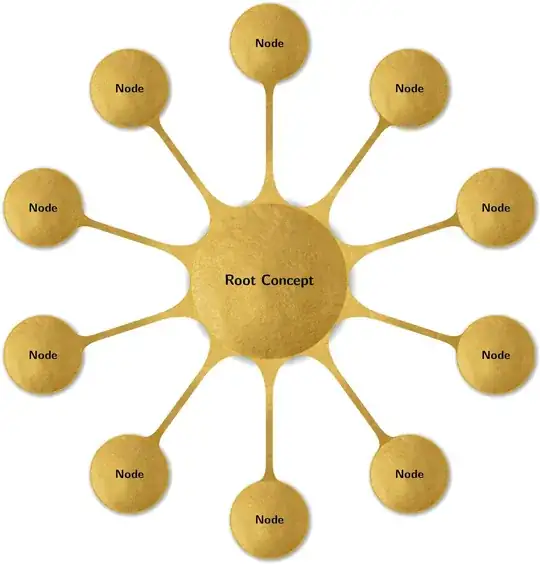
This actually looks better than I though it would.
This is a version that has one overall background picture. Things like shadows do not work as usual. The syntax is
\begin{Mindmap}[<options>]{<graphics>}
 <mindmap code>
\end{Mindmap}
and here is an example:
\documentclass[margin=10pt]{standalone}
\usepackage[dvipsnames,svgnames]{xcolor}
\usepackage{tikz}
\usepackage{environ}
\usetikzlibrary{mindmap,shadows,calc}
\usepackage{fontspec}
\NewEnviron{Mindmap}[2][]{\begin{tikzfadingfrompicture}[name=temp]%
\begin{scope}[transparent!0,mindmap,#1,text=white,concept color=white,
root concept/.append style={concept,concept color=white},
every child/.append style={concept,concept color=white},
local bounding box=Back]
\BODY
\end{scope}
\path let \p1=($(Back.north east)-(Back.south west)+(0.3,0.3)$)
in \pgfextra{\xdef\myx{\x1}\xdef\myy{\y1}};
\end{tikzfadingfrompicture}%
\begin{tikzpicture}[]
\begin{scope}[mindmap,#1,local bounding box=X,opacity=0]%
\BODY
\end{scope}
\fill[white] (X.south west) rectangle (X.north east);
\path[overlay] (X.center)  node[opacity=0,inner sep=0pt] (img)
  {\includegraphics{#2}}
  [path fading=temp,fit fading=false,
  fading transform={shift={(X.center)}}]
  let \p1=($(X.north east)-(X.south west)+(0.3,0.3)$),
  \p2=($(img.north east)-(img.south west)+(0.3,0.3)$) in
   [/utils/exec=\pgfmathsetmacro{\myscale}{max(\x1/\x2,\y1/\y2)}%
   \typeout{\myscale,\x1,\y1,\x2,\y2}]
   (X.center)  node[inner sep=0pt,anchor=center] (img2){%
  \includegraphics[scale=\myscale]{#2}};
  \begin{scope}[mindmap,#1,opacity=0,text opacity=1]%
    \BODY
  \end{scope}
 \end{tikzpicture}%
}
\begin{document}
\begin{Mindmap}[font=\large\bfseries\sffamily,
      grow cyclic,
    every node/.style={concept, circular drop shadow,
    execute at begin node=\hskip0pt},
      root concept/.append style={
        font=\huge\sffamily\bfseries,text width=8cm
    },
      level 1/.append style={sibling angle=360/10,
        font=\bfseries\sffamily\LARGE,
        level distance=35em,
        inner sep=0pt,
        text width=4cm,
        sibling distance=1cm,
        }]{GoldLeaf.jpg}

          \node [root concept] {Root Concept}
         child {node {Node}}
         child {node {Node}}
         child {node {Node}}
         child {node {Node}}
         child {node {Node}}
         child {node {Node}}
         child {node {Node}}
         child {node {Node}}
         child {node {Node}}
         child {node {Node}};
\end{Mindmap}
\end{document}


