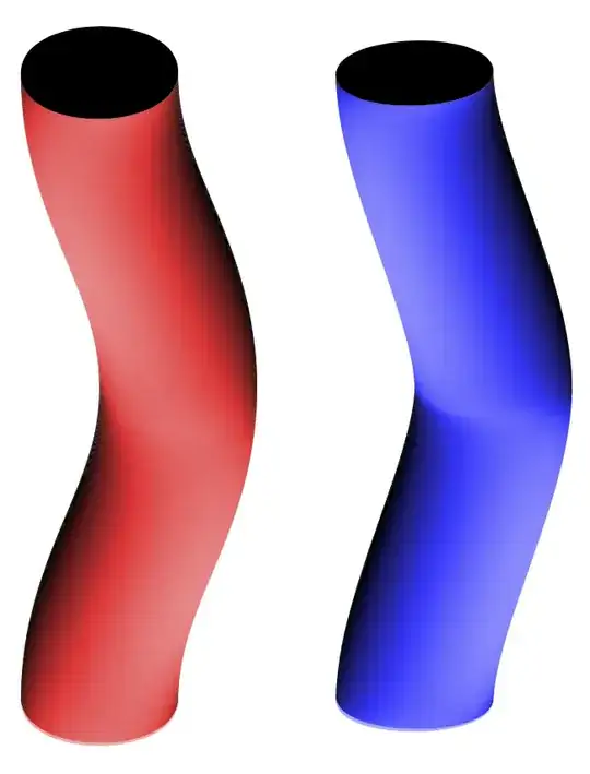
This may (or may not) be a step in the right direction.
\documentclass[tikz,border=3mm]{standalone}
\usetikzlibrary{decorations}
\newcounter{icoord}
\pgfkeys{/tikz/.cd,
    curved cylinder/.cd,
    radius/.store in=\CurvedCylinderRadius,
    radius=10pt,
    step/.store in=\CurvedCylinderStep,
    step=1pt,
    shade/.style={left color=red!30,right color=black,middle color=red!80}
}

\pgfdeclaredecoration{curved cylinder}{initial}
{%
\state{initial}[width=\CurvedCylinderStep,next state=cont] {%
    \pgfmoveto{\pgfpoint{\CurvedCylinderStep}{\CurvedCylinderRadius}}%
    \pgfpathlineto{\pgfpoint{0.3\pgflinewidth}{\CurvedCylinderRadius}}%
    \setcounter{icoord}{0}%
    \pgfcoordinate{lastup-\number\value{icoord}}{\pgfpoint{1pt}{\CurvedCylinderRadius}}%
    \pgfcoordinate{lastdown-\number\value{icoord}}{\pgfpoint{1pt}{-1*\CurvedCylinderRadius}}%
  }
  \state{cont}[width=\CurvedCylinderStep]{%
     \stepcounter{icoord}%
     \pgfcoordinate{lastup-\number\value{icoord}}{\pgfpoint{\CurvedCylinderStep}{\CurvedCylinderRadius}}
     \pgfcoordinate{lastdown-\number\value{icoord}}{\pgfpoint{\CurvedCylinderStep}{-1*\CurvedCylinderRadius}}
     \pgfcoordinate{tmpup}{\pgfpoint{\CurvedCylinderStep+0.3pt}{\CurvedCylinderRadius}}
     \pgfcoordinate{tmpdown}{\pgfpoint{\CurvedCylinderStep+0.3pt}{-1*\CurvedCylinderRadius}}
     \pgfmathanglebetweenlines{\pgfpointanchor{lastup-\the\numexpr\value{icoord}-1}{center}}%
      {\pgfpointanchor{lastup-\number\value{icoord}}{center}}%
      {\pgfpointanchor{Y}{center}}%
      {\pgfpointanchor{O}{center}}%
     \pgfmathsetmacro\myshadingangle{\pgfmathresult}%
     \path[curved cylinder/shade,shading angle=\myshadingangle]
        (lastup-\the\numexpr\value{icoord}-1)
     -- (tmpup) to[out=180,in=180] (tmpdown) -- (lastdown-\the\numexpr\value{icoord}-1)
     to[out=180,in=180] cycle;%
     \pgfmoveto{\pgfpointanchor{lastup-\the\numexpr\value{icoord}-1}{center}}%
     \pgfpathlineto{\pgfpointanchor{lastup-\number\value{icoord}}{center}}%
     \pgfmoveto{\pgfpointanchor{lastdown-\the\numexpr\value{icoord}-1}{center}}%
     \pgfpathlineto{\pgfpointanchor{lastdown-\number\value{icoord}}{center}}%
  }
  \state{final}[width=\CurvedCylinderStep]
  { % perhaps unnecessary but doesn't hurt either
    \pgfmoveto{\pgfpointdecoratedpathlast}
    \fill (tmpup) to[out=0,in=0] (tmpdown) to[out=-180,in=-180] cycle;
  }
}

\begin{document}
  \begin{tikzpicture}[scale=1]
   \path (0,0) coordinate (O) (0,1) coordinate (Y);
    \draw[decorate,decoration=curved cylinder,curved cylinder/radius=1cm]
     (0,0) to[out=90,in=-90] (1,4)  to[out=90,in=-90] (0,8);
    \draw[decorate,decoration=curved cylinder,
        curved cylinder/radius=1cm,
        curved cylinder/shade/.style={left color=blue!30,right
        color=black,middle color=blue!80},looseness=0.7]
     (4,0) to[out=90,in=-90] (5,4)  to[out=90,in=-90] (4,8);
  \end{tikzpicture}
\end{document}
Or
\documentclass[tikz,border=3mm]{standalone}
\usetikzlibrary{decorations}
\newcounter{icoord}
\pgfkeys{/tikz/.cd,
    curved cylinder/.cd,
    radius/.store in=\CurvedCylinderRadius,
    radius=10pt,
    step/.store in=\CurvedCylinderStep,
    step=1pt,
    shade/.style={left color=red!30,right color=black,middle color=red!80}
}

\pgfdeclaredecoration{curved cylinder}{initial}
{%
\state{initial}[width=\CurvedCylinderStep,next state=cont] {%
    \pgfmoveto{\pgfpoint{\CurvedCylinderStep}{\CurvedCylinderRadius}}%
    \pgfpathlineto{\pgfpoint{0.3\pgflinewidth}{\CurvedCylinderRadius}}%
    \setcounter{icoord}{0}%
    \pgfcoordinate{lastup-\number\value{icoord}}{\pgfpoint{1pt}{\CurvedCylinderRadius}}%
    \pgfcoordinate{lastdown-\number\value{icoord}}{\pgfpoint{1pt}{-1*\CurvedCylinderRadius}}%
  }
  \state{cont}[width=\CurvedCylinderStep]{%
     \stepcounter{icoord}%
     \pgfcoordinate{lastup-\number\value{icoord}}{\pgfpoint{\CurvedCylinderStep}{\CurvedCylinderRadius}}
     \pgfcoordinate{lastdown-\number\value{icoord}}{\pgfpoint{\CurvedCylinderStep}{-1*\CurvedCylinderRadius}}
     \pgfcoordinate{tmpup}{\pgfpoint{\CurvedCylinderStep+0.3pt}{\CurvedCylinderRadius}}
     \pgfcoordinate{tmpdown}{\pgfpoint{\CurvedCylinderStep+0.3pt}{-1*\CurvedCylinderRadius}}
     \pgfmathanglebetweenlines{\pgfpointanchor{lastup-\the\numexpr\value{icoord}-1}{center}}%
      {\pgfpointanchor{lastup-\number\value{icoord}}{center}}%
      {\pgfpointanchor{Y}{center}}%
      {\pgfpointanchor{O}{center}}%
     \pgfmathsetmacro\myshadingangle{\pgfmathresult}%
     \path[curved cylinder/shade,shading angle=\myshadingangle]
        (lastup-\the\numexpr\value{icoord}-1)
     -- (tmpup) to[out=180,in=180] (tmpdown) -- (lastdown-\the\numexpr\value{icoord}-1)
     to[out=180,in=180] cycle;%
     \pgfmoveto{\pgfpointanchor{lastup-\the\numexpr\value{icoord}-1}{center}}%
     \pgfpathlineto{\pgfpointanchor{lastup-\number\value{icoord}}{center}}%
     \pgfmoveto{\pgfpointanchor{lastdown-\the\numexpr\value{icoord}-1}{center}}%
     \pgfpathlineto{\pgfpointanchor{lastdown-\number\value{icoord}}{center}}%
  }
  \state{final}[width=\CurvedCylinderStep]
  { % perhaps unnecessary but doesn't hurt either
    \pgfmoveto{\pgfpointdecoratedpathlast}
    \fill (tmpup) to[out=0,in=0] (tmpdown) to[out=-180,in=-180] cycle;
  }
}

\begin{document}
  \begin{tikzpicture}[scale=1]
   \path (0,0) coordinate (O) (0,1) coordinate (Y);
    \draw[decorate,decoration=curved cylinder,curved cylinder/radius=1cm
    ,looseness=0.7]
     (0,0) foreach \X in {1,2,3}
     {to[out=90,in=-90] ++ (1,4)  to[out=90,in=-90] ++(-1,4)};
    \draw[decorate,decoration=curved cylinder,
        curved cylinder/radius=1cm,
        curved cylinder/shade/.style={left color=blue!30,right
        color=black,middle color=blue!80},looseness=0.7]
     (6,0) foreach \X in {1,2,3}
     {to[out=90,in=-90] ++ (-1,4)  to[out=90,in=-90] ++(1,4)};
  \end{tikzpicture}
\end{document}

Even though this is not a full fledged decoration, it still can pick up dimension too large errors easily.


