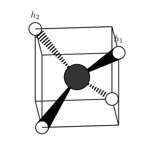
Welcome! Nice question. Here is a way with tangents and clip.
\documentclass[tikz]{standalone}
\usetikzlibrary{backgrounds,positioning}
\usepackage{tikz-3dplot}
\usepackage{chemfig}

\begin{document}
\tdplotsetmaincoords{85}{90}% Determines point of view
\begin{tikzpicture}[tdplot_main_coords,
H atom/.style={circle,fill=hyd,draw=atomshell,thick,inner sep=5pt},
C atom/.style={circle,fill=carb,draw=atomshell,thick,inner sep=10pt}]

\def\c{1.5}

\coordinate (c01) at (0,0,0);

% Cube's edges
\begin{scope}[thick,line join = round]
\draw (\c,\c,\c)  coordinate (h01)
    -- (\c,-\c,\c) coordinate (cor01)
    -- (-\c,-\c,\c) coordinate (h02) -- (-\c,\c,\c) coordinate (cor02)
    -- cycle;
\draw (\c,-\c,-\c) coordinate (h03) edge (cor01)
   -- (-\c,-\c,-\c) coordinate (cor04) edge (cor04)
    -- (-\c,\c,-\c) coordinate (h04) edge (cor02)
    -- (\c,\c,-\c) coordinate (cor03) edge  (h01) -- cycle;
\end{scope}

% Attempt to draw a wedge
\coordinate (h01up) at ($(h01)+(-0.2*\c,-0.2*\c,0)$);
\coordinate (h01do) at ($(h01)+(0,0,-0.2*\c)$);

% Atoms
\colorlet{hyd}{white}
\colorlet{carb}{black!80}
\colorlet{atomshell}{black}

\path (c01) node[C atom]{}
    foreach \X in {1,...,4}
    {\ifnum\X<3
    (h0\X) node[H atom,label=above:{$h_\X$}](H0\X){}
    \else
    (h0\X) node[H atom](H0\X){}
    \fi   } (h02) edge[thick] (cor01);

\begin{scope}[on background layer]
 \begin{scope}[very thick]
  \draw (c01) -- (H03);
  \draw (c01) -- (H04);
 \end{scope}
 \draw[fill] (tangent cs:node=H01, point={(c01)}, solution=1)
  -- (c01) --  (tangent cs:node=H01, point={(c01)}, solution=2);
 \clip (tangent cs:node=H02, point={(c01)}, solution=1)
  -- (c01) --  (tangent cs:node=H02, point={(c01)}, solution=2);
 \draw[line width=15pt,dash pattern={on 1pt off 1pt}] (c01) -- (h02);
\end{scope}
\begin{scope}[xshift = -7.5em, yshift = -6em]
\draw [->] (0,0,0) -- (0.75,0,0) node [below right=-0.2em and -0.2em] {$x$};
\draw [->] (0,0,0) -- (0,0.75,0) node [below left= -0.2em and -0.2em] {$y$};
\draw [->] (0,0,0) -- (0,0,0.6) node [below left] {$z$};
\end{scope}

\node at (0,3.5,0) {\color{blue}\chemfig{(-[:215]H)(-[:325]H)(<[:115]H)(<:[:65]H)}};
\end{tikzpicture}
\end{document}

If you do not want to clip, you can use the expanding waves decoration.
\documentclass[tikz]{standalone}
\usetikzlibrary{backgrounds,positioning,decorations.pathreplacing}
\usepackage{tikz-3dplot}
\usepackage{chemfig}

\begin{document}
\tdplotsetmaincoords{85}{90}% Determines point of view
\begin{tikzpicture}[tdplot_main_coords,
H atom/.style={circle,fill=hyd,draw=atomshell,thick,inner sep=5pt},
C atom/.style={circle,fill=carb,draw=atomshell,thick,inner sep=10pt}]

\def\c{1.5}

\coordinate (c01) at (0,0,0);

% Cube's edges
\begin{scope}[thick,line join = round]
\draw (\c,\c,\c)  coordinate (h01)
    -- (\c,-\c,\c) coordinate (cor01)
    -- (-\c,-\c,\c) coordinate (h02) -- (-\c,\c,\c) coordinate (cor02)
    -- cycle;
\draw (\c,-\c,-\c) coordinate (h03) edge (cor01)
   -- (-\c,-\c,-\c) coordinate (cor04) edge (cor04)
    -- (-\c,\c,-\c) coordinate (h04) edge (cor02)
    -- (\c,\c,-\c) coordinate (cor03) edge  (h01) -- cycle;
\end{scope}

% Attempt to draw a wedge
\coordinate (h01up) at ($(h01)+(-0.2*\c,-0.2*\c,0)$);
\coordinate (h01do) at ($(h01)+(0,0,-0.2*\c)$);

% Atoms
\colorlet{hyd}{white}
\colorlet{carb}{black!80}
\colorlet{atomshell}{black}

\path (c01) node[C atom]{}
    foreach \X in {1,...,4}
    {\ifnum\X<3
    (h0\X) node[H atom,label=above:{$h_\X$}](H0\X){}
    \else
    (h0\X) node[H atom](H0\X){}
    \fi   } (h02) edge[thick] (cor01);

\begin{scope}[on background layer]
 \begin{scope}[very thick]
  \draw (c01) -- (H03);
  \draw (c01) -- (H04);
 \end{scope}
 \draw[fill] (tangent cs:node=H01, point={(c01)}, solution=1)
  -- (c01) --  (tangent cs:node=H01, point={(c01)}, solution=2);
 \draw[decorate,decoration={expanding waves,angle=5,segment length=3pt},very thick]
 (c01) -- (h02);
\end{scope}
\begin{scope}[xshift = -7.5em, yshift = -6em]
\draw [->] (0,0,0) -- (0.75,0,0) node [below right=-0.2em and -0.2em] {$x$};
\draw [->] (0,0,0) -- (0,0.75,0) node [below left= -0.2em and -0.2em] {$y$};
\draw [->] (0,0,0) -- (0,0,0.6) node [below left] {$z$};
\end{scope}
\node at (0,3.5,0) {\color{blue}\chemfig{(-[:215]H)(-[:325]H)(<[:115]H)(<:[:65]H)}};
\end{tikzpicture}
\end{document}

Addendum: just for fun. This requires the 3d tools library. This achieves 3d ordering in a convention-independent way. As long as you have some means that provides you with an oriented orthographic projection of the coordinates, the function screendepth will provide you with the 3d distance from the virtual screen. Coordinates that are closer to the viewer will have a larger screen depth. Tools that achieve orthographic projections include are tikz-3dplot and the perspective library, but their conventions differ. The function here uses the TikZ coordinates. In particular, this also means that we can fully reconstruct the rotation matrix just from TikZ' book keeping variables like \pgf@xx. The following animation shows a possible application. If the bond goes to an object that is further away, it is dashed, if the atoms is closer, it is a wedge and if the atoms are roughly equally far away just at thick line. I payed zero attention to the cube lines.
\documentclass[tikz]{standalone}
\usetikzlibrary{backgrounds,positioning,decorations.pathreplacing,fpu,3dtools}
\usepackage{tikz-3dplot}
\usepackage{chemfig}
\makeatletter
\pgfmathdeclarefunction{screendepth}{1}{%
\begingroup%
\edef\mycoord{\RawCoord(#1)}%
\edef\screenvec{{(\the\pgf@yx)*(\the\pgf@zy)-(\the\pgf@yy)*(\the\pgf@zx)},%
{(\the\pgf@zx)*(\the\pgf@xy)-(\the\pgf@xx)*(\the\pgf@zy)},%
{(\the\pgf@xx)*(\the\pgf@yy)-(\the\pgf@yx)*(\the\pgf@xy)}}%
\pgfkeys{/pgf/fpu,/pgf/fpu/output format=fixed}%
\pgfmathparse{TD("(#1)o(\screenvec)")/1cm/1cm}%
\pgfmathsmuggle\pgfmathresult\endgroup%
}%

\makeatother
\newcommand\ConnectAtoms[3][]{%
\pgfmathsetmacro{\depthA}{screendepth("#2")}%
\pgfmathsetmacro{\depthB}{screendepth("#3")}%
\pgfmathtruncatemacro{\itest}{1+(abs(\depthA-\depthB)<0.1 ?0 : sign(\depthA-\depthB))}%
\ifcase\itest
\draw[decorate,decoration={expanding waves,angle=5,segment length=3pt},
 very thick,#1]
 (#2) -- (#3);
\or
\draw[very thick,#1]
 (#2) -- (#3);
\or
\path[fill,#1] (tangent cs:node=#3, point={(#2)}, solution=1)
  -- (#2) --  (tangent cs:node=#3, point={(#2)}, solution=2);
\fi
}


\begin{document}
\foreach \Angle in {5,15,...,355}
{\tdplotsetmaincoords{90+20*cos(\Angle)}{\Angle}% Determines point of view
\begin{tikzpicture}[tdplot_main_coords,
H atom/.style={circle,fill=hyd,draw=atomshell,thick,inner sep=5pt},
C atom/.style={circle,fill=carb,draw=atomshell,thick,inner sep=10pt}]
% Atoms
\colorlet{hyd}{white}
\colorlet{carb}{black!80}
\colorlet{atomshell}{black}
\path[tdplot_screen_coords,use as bounding box] (-3,-3) rectangle (3,3);
\def\c{1.5}

\path  (0,0,0) coordinate  (c01) node[C atom]{};

% Cube's edges
\begin{scope}[thick,line join = round]
\draw (\c,\c,\c)  coordinate (h01) node[H atom,label=above:{$h_1$}](H01){}
    -- (\c,-\c,\c) coordinate (cor01)
    -- (-\c,-\c,\c) coordinate (h02) node[H atom,label=above:{$h_2$}](H02){}
    -- (-\c,\c,\c) coordinate (cor02)
    -- cycle;
\draw (\c,-\c,-\c) coordinate (h03) node[H atom](H03){}
   -- (-\c,-\c,-\c) coordinate (cor04) edge (H02)
    -- (-\c,\c,-\c) coordinate (h04) node[H atom](H04){}
    -- (\c,\c,-\c) coordinate (cor03) edge  (H01) -- cycle
    (cor01) edge (H03)
    (cor02) edge (H04);
\end{scope}


\path (h02) edge[thick] (cor01)
    (h04) edge[thick] (cor03);
\pgfmathsetmacro{\depthA}{screendepth("c01")}%
\pgfmathsetmacro{\depthB}{screendepth("h03")}%
\begin{scope}[on background layer]
 \foreach \X in {1,2,3,4}
 {\ConnectAtoms{c01}{H0\X}}
\end{scope}
\end{tikzpicture}}
\end{document}


3dtoolslibrary, are you willing to load it? – Apr 10 '20 at 15:493dtools, but for today it doesn't seem necessary. The edges worked on my piece-wise drawing above, and in your code I think it's just because of doing these two lines at the end of their block:\fi } (h02) edge[thick] (cor01)(h04) edge[thick] (cor03);– methaneman Apr 10 '20 at 16:01(h02)is "further back" than(cor01). Yet I think I agree that the second edge should not be there. – Apr 10 '20 at 16:11