First of all --- I think you found a bug. I will look into it as soon as I can. But probably the bug is not what you think --- you shouldn't have the bottom pin on your DQBP, and you should have the reset pin on your DQBR flip-flop.
(side note --- I suggest you use Q and the not ball, or \ctikztextnot{Q} without the not ball. People can think that there is a double negation there).
Second of all, the solution you found for the connection to the ball is the correct one, not an ugly hack --- it is explained in the manual (bottom of page 130), when you have 0 length external pins --- in your case, you have the same situation due to the bug.
The theory is that when you say nd=1 (or nu=1) to have the negated ball, the external pin is drawn also. When drawing the external pin, the pin/ball overlap is taken into account in the shape.
What you really want here is having the pins, so the first and second rows work naturally. As a workaround, add a blank label to the pin for DQBR and DQBP.
DQ has no upper or down pins, so you have to use the border anchors.
\documentclass[border=4pt]{standalone}
\usepackage{tikz}
\usepackage[RPvoltages]{circuitikz}
\tikzset{flipflop DQ/.style={flipflop, scale=.7,
         flipflop def={t1=D, t6=Q, c3=1,
         clock wedge size=.3, font=\normalsize}
}}
\tikzset{flipflop DQBR/.style={flipflop, scale=.7, % Has D, Q, QBar and Reset
         flipflop def={t1=D, t6=Q, c3=1, t4=\ctikztextnot{Q}, n4=1, nd=1, td=~,
         clock wedge size=.3, font=\normalsize},
}}
\tikzset{flipflop DQBP/.style={flipflop, scale=.7, % Has D, Q, QBar and Preset
         flipflop def={t1=D, t6=Q, c3=1, t4=\ctikztextnot{Q}, n4=1, nu=1, tu=~,
         clock wedge size=.3, font=\normalsize}
}}
\begin{document}
\begin{circuitikz}
  \node[flipflop DQBR] (ff0) at (0,3) {0};
  \node[flipflop DQBR] (ff1) at (3,3) {1};
  \node[flipflop DQBR] (ff2) at (6,3) {2};
  \node[flipflop DQBP] (ff3) at (0,0) {3};
  \node[flipflop DQ]   (ff4) at (3,0) {4};
  \node[flipflop DQ]   (ff5) at (6,0) {5};
\draw (ff0.down) -- (ff3.up);
  \draw (ff1.down) -- (ff4.bup);
  \draw (ff2.down) -- (ff5.bup);
\end{circuitikz}
\end{document}

PD the bug is just a silly typo (I can say that because I wrote it!)
diff --git a/tex/pgfcircmultipoles.tex b/tex/pgfcircmultipoles.tex
index 3454f6d..82b156c 100644
--- a/tex/pgfcircmultipoles.tex
+++ b/tex/pgfcircmultipoles.tex
@@ -1406,7 +1406,7 @@
                 \ifx\@@tmp\@@x\else\edef\@@or{1}\fi
                 \edef\@@tmp{\ctikzvalof{multipoles/flipflop/cd}}
                 \ifnum\@@tmp>0\edef\@@or{1}\fi
-                \edef\@@tmp{\ctikzvalof{multipoles/flipflop/nu}}
+                \edef\@@tmp{\ctikzvalof{multipoles/flipflop/nd}}
                 \ifnum\@@tmp>0\edef\@@or{1}\fi
                 % \typeout{TEST\space\@@tmp\space\@@x}
                 \ifnum\@@or>0
with the patch in (it will be fixed in v1.3.2), your original code (with the connection in red to show them better) works almost out of the box:
\documentclass[border=4pt]{standalone}
\usepackage{tikz}
\usepackage[RPvoltages]{circuitikz}
\tikzset{flipflop DQ/.style={flipflop, scale=.7,
         flipflop def={t1=D, t6=Q, c3=1,
         clock wedge size=.3, font=\normalsize}
}}
\tikzset{flipflop DQBR/.style={flipflop, scale=.7, % Has D, Q, QBar and Reset
         flipflop def={t1=D, t6=Q, c3=1, t4=\ctikztextnot{Q}, n4=1, nd=1,
         clock wedge size=.3, font=\normalsize},
}}
\tikzset{flipflop DQBP/.style={flipflop, scale=.7, % Has D, Q, QBar and Preset
         flipflop def={t1=D, t6=Q, c3=1, t4=\ctikztextnot{Q}, n4=1, nu=1,
         clock wedge size=.3, font=\normalsize}
}}
\begin{document}
\begin{circuitikz}
  \node[flipflop DQBR] (ff0) at (0,3) {0};
  \node[flipflop DQBR] (ff1) at (3,3) {1};
  \node[flipflop DQBR] (ff2) at (6,3) {2};
  \node[flipflop DQBP] (ff3) at (0,0) {3};
  \node[flipflop DQ]   (ff4) at (3,0) {4};
  \node[flipflop DQ]   (ff5) at (6,0) {5};
\draw[red] (ff0.down) -- (ff3.up);
  \draw[red] (ff1.down) -- (ff4.bup);
  \draw[red] (ff2.down) -- (ff5.bup);
\end{circuitikz}
\end{document}
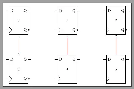
Sorry for the horrible antialiasing, blame okular
 Note that the left connection overwrites the bubble, the center one misses, and only the right one connects nicely. Contrast that with the flip-flop on the left bottom, where the line connecting to the up anchor intersects cleanly with the bubble.
