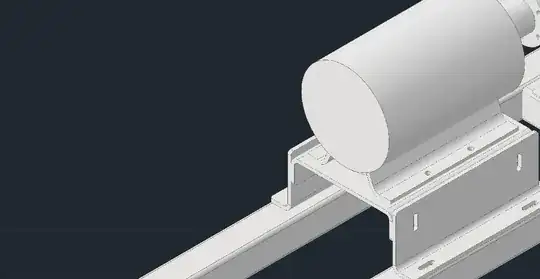
First of all. Never nest tikzpictures! And post the basic picture, which in this case I managed to concoct with GIMP and saved as uffa.png.
My approach would be:
- load the image as a node at the start of the
tikzpicture, so that then you can write on top of it.
- Set some kind of grid to have an easy reference.
- Draw whatever you want, fine tune coordinates.
- Remove the grid.
Let's see: step 1 & 2 would be something like this:
\documentclass[tikz]{standalone}
\begin{document}
\begin{tikzpicture}
    \node[anchor=south west,inner sep=0] (image) at (0,0) {%
        \includegraphics[width=10cm]{uffa.png}};
        \draw[red,thin] (0,0) grid[step=1] (10,5);
\end{tikzpicture}
\end{document}

You have 0,0 on the bottom left point, and every grid step is 1cm. Now, the background is not white (I hope you do not print it, otherwise, change it), so I picked the color that results to be a quite dark blue-grey with RGB at 33,40,48 (any color picker will do).
Now I draw the circuit, setting the blue-gray as the fill for open poles.
\documentclass[tikz]{standalone}
\usepackage[RPvoltages, american]{circuitikz}
\begin{document}
\begin{tikzpicture}[color=white]% write in white
    \node[anchor=south west,inner sep=0] (image) at (0,0) {%
        \includegraphics[width=10cm]{uffa.png}};
        \draw[red,thin] (0,0) grid[step=1] (10,5);
        \definecolor{mybg}{RGB}{33,40,48}% with a color picker
        \ctikzset{open poles fill=mybg}% tell circuitikz what is background for you
        \draw (4,4) coordinate(a) to[short, i=$i_a$, o-]  ++(1.8,0);
        \draw (a) ++(0,-1) to[short, o-] ++(1.7,0);
        \draw (a) ++(-0.3,0) to[open, v=$v$] ++(0,-1);
\end{tikzpicture}
\end{document}

I tried to use relative and named coordinates where possible, to minimize the number of numbers you need to tweak to obtain the result. Then, you remove the grid and you'll have:


circuitikzis the same astikzpicture. – Rmano Oct 09 '22 at 10:51