For comparison, here is a version in Metapost showing how to do reflection.
This is wrapped up with luamplib so you need to compile it with lualatex.
\documentclass[border=5mm]{standalone}
\usepackage{luamplib}
\begin{document}
\mplibtextextlabel{enable}
\begin{mplibcode}
beginfig(1);
path A, B;
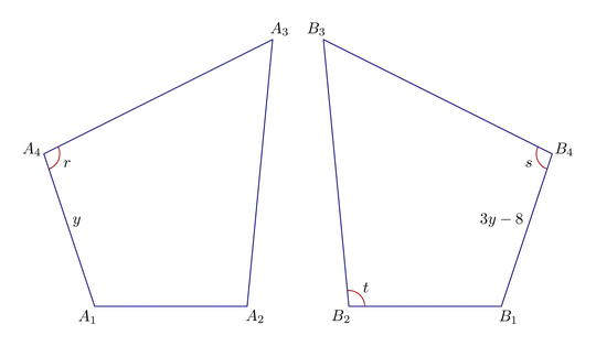
A = origin -- (32, -96) -- (128, -96) -- (144, 72) -- cycle;
A := A shifted 160 left;
B = A reflectedabout(up, down);
vardef add_angle_label(expr a, o, b, r, t) =
save arc; path arc;
arc = fullcircle scaled 2r rotated angle (a-o) shifted o cutafter (o..b);
draw arc withcolor 3/4 red;
label(t, beyond(o, point arctime 1/2 arclength arc of arc of arc, 6));
enddef;
vardef median(expr p) = save n; numeric n; n = length p;
origin for i=1 upto n: + point i of p scaled (1/n) endfor enddef;
vardef beyond(expr a, b, o) = save d; d = abs(b-a); (1+o/d)[a, b] enddef;
add_angle_label(point 1 of A, point 4 of A, point 3 of A, 10, "$r$");
add_angle_label(point 3 of B, point 4 of B, point 1 of B, 10, "$s$");
add_angle_label(point 1 of B, point 2 of B, point 3 of B, 10, "$t$");
forsuffixes $=A, B:
pair m; m = median($);
draw $ withcolor 1/2 blue;
for i=1 upto 4:
label("$" & str $ & "_" & decimal i & "$", beyond(m, point i of $, 8));
endfor
endfor
label.urt ("$y$", point 1/2 of A);
label.ulft("$3y-8$", point 1/2 of B);
endfig;
\end{mplibcode}
\end{document}
Notes
The first <path> variable A is created like this:
A = origin -- (32, -96) -- (128, -96) -- (144, 72) -- cycle;
then shifted so it is the left of the origin (note that you have to use := to update it).
A := A shifted 160 left;
Then the second <path> variable B is created in one go:
B = A reflectedabout(up, down);
Then I've added a couple of useful macros:
add_angle_label creates an appropriate circular arc, draws it in red, and then adds the label t half way along it.
median gives you a weighted central point for any cyclic polygon path -- a bit more useful than center if the shape is irregular.
beyond(a, b, o) returns a <pair> that is o pt beyond b in the direction of a--b.
Finally the shapes and labels are drawn in a nested loop.
 I write this code, but I can't define mirror nodes based on nodes A1 ... A4.


tikz-euclide. – Tolaso Apr 25 '23 at 04:06