You want to load the positioning library (→ manual) and use the appropriate keys:
\begin{tikzpicture}[node distance=1cm and 1cm, on grid, math nodes]
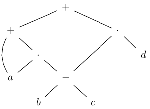
\node (P0) {+};
\node[below left=1cm and 2cm of P0] (P1) {+};
\node[below right=1cm and 2cm of P0] (M0) {\cdot};
\node[below right= of P1] (M1) {\cdot};
\node[below right= of M1] (m0) {-};
\node[below left= of M1] (a) {a};
\node[below left= of m0] (b) {b};
\node[below right= of m0] (c) {c};
\node[below right= of M0] (d) {d};
\path (P0) edge (P1) edge (M0)
(P1) edge (M1) edge[bend right] (a)
(M0) edge (m0) edge (d)
(M1) edge (m0) edge (a)
(m0) edge (b) edge (c);
\end{tikzpicture}
Notice how I've used 1cm and 2cm with P1 and M0? This is double the horizontal space but the same vertical distance compared to the default node distance 1cm and 1cm.
When the ext.positioning-plus is loaded, one can use
\node[below  left=1 and 2:of P0] (P1) {+};
\node[below right=1 and 2:of P0] (M0) {\cdot};
where the part before the : denotes a factor the default node distance should be multiplied with. This allows you to later change the default node distance in the options of the TikZ picture without having to go through all nodes and correct the hard-coded distances yourself.
I always add text depth = 0pt and text height = .7em so that the nodes are aligned better.
That said, I think you're better off placing the nodes in a matrix. The tikzcd package loaded with the cd library makes this very convenient.
\begin{tikzcd}[sep=small, arrows=dash]
 & & +         \ar[dll] \ar[drr]           \\
+              \ar[dr] \ar[dd, bend right]
 & & & & \cdot \ar[dr] \ar[ddll]           \\
 & \cdot       \ar[dl] \ar[dr]
   & & & & d                              \\
a  & & -       \ar[dl] \ar[dr]             \\
 & b
   & & c
\end{tikzcd}
This way, your diagram is built like a tabular or an array. The \ar macro is used to place the edges between the nodes. It accepts the same options as a to path like bend right. With the keys d, l, u and r you specify the target node.
Code
\documentclass[tikz]{standalone}
%\documentclass{article}
%\usepackage{tikz}
\usetikzlibrary{cd, positioning, ext.positioning-plus}
\tikzset{math nodes/.style={execute at begin node=$, execute at end node=$}}
\begin{document}
\begin{tikzcd}[sep=small, arrows=dash]
 & & +         \ar[dll] \ar[drr]           \\
+              \ar[dr] \ar[dd, bend right]
 & & & & \cdot \ar[dr] \ar[ddll]           \\
 & \cdot       \ar[dl] \ar[dr]
   & & & & d                              \\
a  & & -       \ar[dl] \ar[dr]             \\
 & b
   & & c
\end{tikzcd}
\begin{tikzpicture}[
  node distance=1cm and 1cm, on grid, math nodes,
  text depth=+0pt, text height=+.7em]
\node                                (P0) {+};
\node[below  left=1cm and 2cm of P0] (P1) {+};
\node[below right=1cm and 2cm of P0] (M0) {\cdot};
\node[below right=            of P1] (M1) {\cdot};
\node[below right=            of M1] (m0) {-};
\node[below  left=            of M1] (a)  {a};
\node[below  left=            of m0] (b)  {b};
\node[below right=            of m0] (c)  {c};
\node[below right=            of M0] (d)  {d};
\path (P0) edge (P1) edge (M0)
      (P1) edge (M1) edge[bend right] (a)
      (M0) edge (m0) edge (d)
      (M1) edge (m0) edge (a)
      (m0) edge (b) edge (c);
\end{tikzpicture}
\begin{tikzpicture}[
  node distance=8mm and 8mm, on grid, math nodes,
  text depth=+0pt, text height=+.7em]
\node                            (P0) {+};
\node[below  left=1 and 2:of P0] (P1) {+};
\node[below right=1 and 2:of P0] (M0) {\cdot};
\node[below right=        of P1] (M1) {\cdot};
\node[below right=        of M1] (m0) {-};
\node[below  left=        of M1] (a)  {a};
\node[below  left=        of m0] (b)  {b};
\node[below right=        of m0] (c)  {c};
\node[below right=        of M0] (d)  {d};
\path (P0) edge (P1) edge (M0)
      (P1) edge (M1) edge[bend right] (a)
      (M0) edge (m0) edge (d)
      (M1) edge (m0) edge (a)
      (m0) edge (b) edge (c);
\end{tikzpicture}
\end{document}
Output
(They're all relatively the same.)


node distance=4cmas option to(secondLeft)and(secondRight)(and something likeyshift=1cmif you feel that the vertical distance is too large). – Jasper Habicht Jul 02 '23 at 10:21positioninglibrary you can dobelow=of thirdLeft -| firstwherethirdLeft -| firstdenotes a points that lies on the intersection between a horizontal through thirdLeft and a vertical of first. – Qrrbrbirlbel Jul 02 '23 at 13:28