2

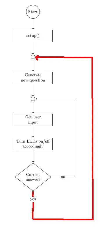
Can anyone please help me how to draw the arrow in red?

Example

\documentclass{article}
\pagestyle{empty} % do not print page number
\usepackage{tikz}
\usetikzlibrary{shapes.geometric, arrows}
\pagecolor{white}

\tikzset { startstop/.style={ circle, rounded corners, minimum width=1cm, minimum height=1cm, text centered, draw=black!80, fill=white!100 }, interconnect/.style={ circle, minimum width=0.25cm, minimum height=0.25cm, draw=black!80, fill=white!100 }, process/.style={ rectangle, minimum width=3cm, minimum height=1cm, text centered, text width=3cm, draw=black!80, fill=white!100 }, decision/.style={ diamond, minimum width=3cm, minimum height=1cm, text centered, draw=black!80, fill=white!100 }, % RECTANGULAR CONNECTOR ---------------------------------------------------------------------------- % from: https://tex.stackexchange.com/questions/50780/arrows-at-right-angles-on-a-tikzpicture-matrix descr/.style={ fill=white, inner sep=2.5pt }, connector/.style={ -latex }, rectangle connector/.style={ connector, to path={(\tikztostart) -- ++(#1,0pt) \tikztonodes |- (\tikztotarget) }, pos=0.5 }, rectangle connector/.default=-2cm, straight connector/.style={ connector, to path=--(\tikztotarget) \tikztonodes }, % -------------------------------------------------------------------------------------------------- arrow/.style={thick,->,>=stealth} }

\begin{document}

\begin{tikzpicture}[node distance=2cm]

\node (START) [startstop] {Start}; \node (SETUP) [process, below of=START, yshift=0.0cm] {setup()}; \node (CON1) [interconnect, below of=SETUP, yshift=0.25cm] {}; \node (GEN-QUEST) [process, below of=CON1, align=center, yshift=0.25cm] {Generate\new question}; \node (CON2) [interconnect, below of=GEN-QUEST, yshift=0.25cm] {}; \node (INPUT) [process, below of=CON2, align=center, yshift=0.25cm] {Get user\input}; \node (LED) [process, below of=INPUT, align=center] {Turn LEDs on/off\accordingly}; \node (CHECK-ANSWER) [decision, below of=LED, align=center, yshift=-0.75cm] {Correct\answer?};

\draw [arrow] (START) -- (SETUP); \draw [arrow] (SETUP) -- (CON1); \draw [arrow] (CON1) -- (GEN-QUEST); \draw [arrow] (GEN-QUEST) -- (CON2); \draw [arrow] (CON2) -- (INPUT); \draw [arrow] (INPUT) -- (LED); \draw [arrow] (LED) -- (CHECK-ANSWER); \draw [rectangle connector=3.5cm] (CHECK-ANSWER) to node[descr] {no} (CON2);

\end{tikzpicture} \end{document}

2 Answers2

1

As variation to the existing rectangle connector, you can define another style:

double rectangle connector/.style={
    connector,
    to path={(\tikztostart) |- ++(#1) \tikztonodes |- (\tikztotarget)},
    pos=0.25
},
double rectangle connector/.default={2cm,-2cm},

And then add to your drawing:

\draw [double rectangle connector={5cm,-2cm}] (CHECK-ANSWER) to node[descr] {yes} (CON1);

MWE:

\documentclass[border=10pt]{standalone}
\usepackage{tikz}
\usetikzlibrary{shapes.geometric}

\tikzset { startstop/.style={ circle, rounded corners, minimum width=1cm, minimum height=1cm, text centered, draw=black!80, fill=white!100 }, interconnect/.style={ circle, minimum width=0.25cm, minimum height=0.25cm, draw=black!80, fill=white!100 }, process/.style={ rectangle, minimum width=3cm, minimum height=1cm, text centered, text width=3cm, draw=black!80, fill=white!100 }, decision/.style={ diamond, minimum width=3cm, minimum height=1cm, text centered, draw=black!80, fill=white!100 }, % RECTANGULAR CONNECTOR ---------------------------------------------------------------------------- % from: https://tex.stackexchange.com/questions/50780/arrows-at-right-angles-on-a-tikzpicture-matrix descr/.style={ fill=white, inner sep=2.5pt }, connector/.style={ -latex }, rectangle connector/.style={ connector, to path={(\tikztostart) -- ++(#1,0pt) \tikztonodes |- (\tikztotarget)}, pos=0.5 }, rectangle connector/.default=-2cm, double rectangle connector/.style={ connector, to path={(\tikztostart) |- ++(#1) \tikztonodes |- (\tikztotarget) }, pos=0.25 }, double rectangle connector/.default={2cm,-2cm}, straight connector/.style={ connector, to path=--(\tikztotarget) \tikztonodes }, % -------------------------------------------------------------------------------------------------- arrow/.style={thick, ->, >=stealth} }

\begin{document}

\begin{tikzpicture}[node distance=2cm]

\node (START) [startstop] {Start}; \node (SETUP) [process, below of=START, yshift=0.0cm] {setup()}; \node (CON1) [interconnect, below of=SETUP, yshift=0.25cm] {}; \node (GEN-QUEST) [process, below of=CON1, align=center, yshift=0.25cm] {Generate\new question}; \node (CON2) [interconnect, below of=GEN-QUEST, yshift=0.25cm] {}; \node (INPUT) [process, below of=CON2, align=center, yshift=0.25cm] {Get user\input}; \node (LED) [process, below of=INPUT, align=center] {Turn LEDs on/off\accordingly}; \node (CHECK-ANSWER) [decision, below of=LED, align=center, yshift=-0.75cm] {Correct\answer?};

\draw [arrow] (START) -- (SETUP); \draw [arrow] (SETUP) -- (CON1); \draw [arrow] (CON1) -- (GEN-QUEST); \draw [arrow] (GEN-QUEST) -- (CON2); \draw [arrow] (CON2) -- (INPUT); \draw [arrow] (INPUT) -- (LED); \draw [arrow] (LED) -- (CHECK-ANSWER); \draw [rectangle connector=3.5cm] (CHECK-ANSWER) to node[descr] {no} (CON2); \draw [double rectangle connector={5cm,-2cm}] (CHECK-ANSWER) to node[descr] {yes} (CON1);

\end{tikzpicture} \end{document}

enter image description here

1

A bit more sophisticated code, which is based on the use of the TikZ libraries chains, positioning and ext.paths.ortho. Due to them the code is much shorter and concise:

  • nodes are connected in vertical chain, where are by use of the macro join are connected by arrows
  • for feedback are used ext.paths.ortho library (it is part of tikz-ext package)
\documentclass[border=3mm]{standalone}
\usepackage{tikz}
\usetikzlibrary{arrows.meta,
                chains,
                ext.paths.ortho,    % defined in the tikz-ext package
                positioning,
                quotes,
                shapes.geometric}

\tikzset { arr/.style = {-Stealth}, base/.style = {draw=black!80, align=center}, startstop/.style = {base, circle, minimum size=1cm}, interconnect/.style = {base, circle, minimum size=2.5mm, node contents = {}}, process/.style = {base, minimum width=3cm, minimum height=1cm}, decision/.style = {base, diamond, minimum width=3cm, minimum height=1cm}, lbl/.style = {fill=white, font=\footnotesize, inner sep=2pt, pos=#1} }

\begin{document}

\begin{tikzpicture}[

node distance = 4mm and 12mm, start chain = going below ] \begin{scope}[nodes={on chain, join=by arr}] \node (START) [startstop] {Start}; \node (SETUP) [process] {setup()}; \node (CON1) [interconnect]; \node (GEN-QUEST) [process] {Generate\new question}; \node (CON2) [interconnect]; \node (LED) [process] {Turn LEDs on/off\accordingly}; \node (CHECK-ANSWER) [decision] {Correct\answer?}; \end{scope} % arrows not included in join macro \draw[arr] (CHECK-ANSWER) r-rl[rl distance=12mm] (CON2) node[lbl=0.1] {No}; \draw[arr] (CHECK-ANSWER.south) -- ++ (0,-1) node[lbl=0.5] {Yes} r-rl[rl distance=28mm] (CON1); \end{tikzpicture} \end{document}

enter image description here

Zarko
  • 296,517