I agree with Dave which suggest to directly draw the picture with TikZ: on the site you will find lots of starting points (one could be define one style module customizable for the colors and then use a matrix to position the nodes, or just place them via the positioning library - perhaps someone will post another answer).
I prefer another way because this is something that could be done easily also in a object-oriented fashion. The problem, or the beauty of the approach (I see it more in this way), is that one should implement itself all.
The code is commented, so it is possible to follow the reasoning behind.
\documentclass{beamer}
\usepackage{lmodern}

\usepackage{tikz}
\usepgfmodule{oo}
\usetikzlibrary{positioning}

\pgfooclass{module}{

 % class attributes
 \attribute text;
 \attribute text width=2.5cm;
 \attribute border color=orange;
 \attribute top color=none;
 \attribute bottom color=none;
 \attribute text color=black;
 \attribute label;
 \attribute width=3cm;
 \attribute height=1cm;

 % constructor method
 \method module() {
 }

 \method text(#1) {
  \pgfooset{text}{#1}
 }

 \method set text width(#1) {
  \pgfooset{text width}{#1}
 }

 \method set border color(#1) {
  \pgfooset{border color}{#1}
 }

 \method set top color(#1) {
  \pgfooset{top color}{#1}
 }

 \method set bottom color(#1) {
  \pgfooset{bottom color}{#1}
 }

 \method set text color(#1) {
  \pgfooset{text color}{#1}
 }

 \method set label(#1) {
  \pgfooset{label}{#1}
 }

 \method set width(#1) {
  \pgfooset{width}{#1}
 }

 \method set height(#1) {
  \pgfooset{height}{#1}
 }

 \method draw(#1,#2) {
  \node [rectangle,
    rounded corners,
    draw=\pgfoovalueof{border color},
    top color=\pgfoovalueof{top color},
    bottom color=\pgfoovalueof{bottom color},
    text=\pgfoovalueof{text color},
    align=center,
    text width=\pgfoovalueof{text width},
    minimum width=\pgfoovalueof{width},
    minimum height=\pgfoovalueof{height},
    ] (\pgfoovalueof{label}) at (#1,#2) {\pgfoovalueof{text}};
 }

 \method place(#1) {
  \node [rectangle,
    rounded corners,
    draw=\pgfoovalueof{border color},
    top color=\pgfoovalueof{top color},
    bottom color=\pgfoovalueof{bottom color},
    text=\pgfoovalueof{text color},
    align=center,
    text width=\pgfoovalueof{text width},
    minimum width=\pgfoovalueof{width},
    minimum height=\pgfoovalueof{height},
    #1
    ] (\pgfoovalueof{label}) {\pgfoovalueof{text}};
 }

 % shortcut method to easily set labels, text and draw
 % use the \pgfoothis to refer to the current object
 \method set and draw(#1,#2,#3,#4) {
  \pgfoothis.set label(#1)
  \pgfoothis.text(#2)
  \pgfoothis.draw(#3,#4)
 }

 % shortcut method to easily set labels, text and place
 % objects
 \method set and place(#1,#2,#3) {
  \pgfoothis.set label(#1)
  \pgfoothis.text(#2)
  \pgfoothis.place(#3)
 }

 % shortcut method to easily set the style
 \method set style(#1,#2,#3) {
  \pgfoothis.set border color(#1)
  \pgfoothis.set top color(#2)
  \pgfoothis.set bottom color(#3)
 }

 % shortcut method to easily set the dimensions
 \method set dimensions(#1,#2,#3) {
  \pgfoothis.set width(#1)
  \pgfoothis.set height(#2)
  \pgfoothis.set text width(#3)
 }

}

\begin{document}
\begin{frame}{Lowering Flow Overview}
\begin{tikzpicture}[node distance=1.5cm,scale=0.75, transform shape]
% declaring the new object with the constructor method
\pgfoonew \mod=new module()

% method set style:
% #1= border color
% #2= top color
% #3= bottom color
\mod.set style(blue,blue!40,blue!5)

% method set and draw:
% #1= label of the node
% #2= text
% #3,#4= coordinates
\mod.set and draw(mod1,LLVM IR,0,0)

\mod.set style(blue!50!cyan,blue!50!cyan!40,blue!50!cyan!5)

% method set dimensions:
% #1= module width
% #2= module height
% #3= text width
\mod.set dimensions(5cm,1cm,4.9cm)

% method set and place:
% #1= label of the node
% #2= text
% #3= position with respect to another node identified with a label
\mod.set and place(mod2,{\mbox{DAG of Target Operation} (might be illegal)} ,below of=mod1)
\mod.set and place(mod3,{\mbox{DAG of Target Operation} (legal)} ,below of=mod2)

\mod.set style(green!30!lime,green!30!lime!40,green!30!lime!5)
\mod.set and place(mod4,{\mbox{DAG of Machine}\\ Instructions} ,below of=mod3)

\mod.set style(orange,orange!40,orange!5)
\mod.set and place(mod5,{Sequence \mbox{of Machine} Instructions} ,below of=mod4)

\mod.set dimensions(3.25cm,1cm,3cm)
\mod.set style(violet!80!purple,violet!80!purple!40,violet!80!purple!5)
\mod.set and place(mod6,{Object File} ,right=3cm of mod1)

\mod.set and place(mod7,{Assembly File} ,below right=0.75cm of mod6)

\mod.set dimensions(5cm,1cm,4.9cm)
\mod.set style(red,red!40,red!5)
\mod.set and place(mod8,{\mbox{Machine Code Layer}\\ (MCInst)} ,below =2cm of mod6)

\mod.set style(orange,orange!40,orange!5)
\mod.set and place(mod9,{Sequence \mbox{of Machine} Instructions} ,below of=mod8)

% since here we repeat the same text we just need to place the object
\mod.place(below of=mod9)
\end{tikzpicture}
\end{frame}
\end{document}
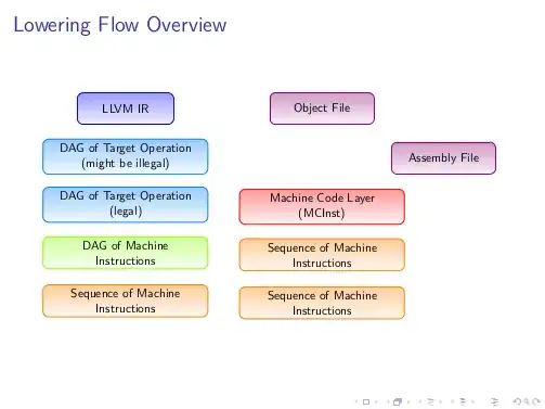
The result: