Next you have a possible solution. I've built your diagram from bottom to top, because I thought it was easier this way. I've included some comments inside the code to explain how I did it.
\documentclass[tikz,border=3mm]{standalone}
\usepackage{tikz}
\usepackage{xcolor}
\usepackage{varwidth}
\usetikzlibrary{calc,positioning,shapes.geometric,shapes,arrows,chains,mindmap,trees,backgrounds}
\def\ns{\nodepart{second}}


\begin{document}
\tikzstyle{struc}=[rectangle split, rectangle split parts=2,minimum height = 2.5cm, minimum width=1.9cm,inner sep=1pt, text width= 1.8cm, text centered,inner sep=0.15cm, font=\scriptsize\bfseries]
\tikzstyle{agg}=[rectangle,draw=black,fill=white,struc]
\tikzstyle{disc}=[rectangle,draw=black,fill=blue!10,struc,anchor=north]
\tikzstyle{cred}=[rectangle,draw=black,fill=gray!20,struc,anchor=north]
\tikzstyle{comb}=[rectangle,draw=red,fill=yellow!50,dashed,struc,anchor=north]

\begin{tikzpicture}

% We start with third row.
% All boxes will be top aligned with `right= of xxx.north, anchor=north`
%
\begin{scope}[node distance=3mm]
    \node [disc] (ap) {PLorem ipsum dolor sit amet. \ns 10\%};
    \node [disc,right= of ap.north east,anchor=north west] (oth) {Lorem ipsum dolor sit amet. \ns a};
    \node [cred,right= of oth.north east, anchor=north west] (osp) {Cras eros lectus, euismod et tristique a, vehicula. \ns a};
    \node [disc,right= of osp.north east,anchor=north west] (ond) {Neque porro quisquam est qui\ns a};
    \node [cred,right= of ond.north east,anchor=north west] (ospb) {Neque porro quisquam est qui\ns a};
    \node [disc,right= of ospb.north east,anchor=north west] (ofxe) {Lorem ipsum dolor\ns a};
    \node [disc,below=0.25cm of ofxe,anchor=north] (ofe) {Lorem ipsum dolor\ns a};
    \node [disc,right= of ofxe.north east,anchor=north west] (shfp) {tristique a, vehicula\ns a};
    \node [disc,right=of shfp.north east,anchor=north west] (gifp) {tristique a, vehiculao \ns a};
    \node [disc,right= of gifp.north east,anchor=north west] (ulonp) {Cras eros lectus, euismod et tristique a, vehicula \ns a};
    \node [disc,right= of ulonp.north east,anchor=north west] (ulofp) {Cras eros lectus, euismod et tristique a, vehicula \ns a};
\end{scope}

% Next right part of second row on top of third with `above=of ...`
\begin{scope}[node distance=25mm]
\node [agg,above=of ofxe.north,anchor=north](npof){Lorem ipsum dolor\ns 2\%};
\node [agg,above=of shfp,anchor=north] (shf){Lorem ipsum dolor \ns 1\%};
\node [agg,above=of gifp.north, anchor=north](gif){Gtristique a, vehicula\ns 1\%};
\node [agg,above=of ulonp.north, anchor=north](ulon){Neque porro quisquam est qui \ns 0.5\%};
\node [agg,above=of ulofp.north, anchor=north](ulof){Neque porro quisquam est qui \ns 0.5\%};
\end{scope}

% Left part of second row.
% We define an auxiliary coordiante to be used as abscissa
\coordinate (aux1) at ($(ap.north)!0.5!(oth.north)$);

% We place the node at abscissa of `aux1` and ordinate of `npof.north`
\node [agg,anchor=north] (par) at (aux1|-npof.north) {Lorem ipsum dolor sit amet \ns 90\%};

% Repeat the previos process
\coordinate (aux2) at ($(ospb.north)!0.5!(ond.north)$);
\node [agg,anchor=north] (npon) at (aux2|-npof.north) {Neque porro quisquam est qui\ns 5\%};

% And repeat for first row.
\coordinate (aux3) at ($(par.north)!0.5!(npon.north)$);
% We don't have an horizontal reference, so `yshift` is used.
\node [agg, anchor=north] (ltd) at ([yshift=20mm]aux3) {abcde fghij \nodepart{second} 100\%};

\end{tikzpicture}

\end{document}
Second version:
After some more work, I've managed to build it from top to bottom.
First a little bit of cleaning on preamble. I use standalone package with tikz option which already charges TikZ. TikZ already includes xcolor, so no need for \usepackage{xcolor}. And, because this MWE doesn't need varwidth, I've also deleted it. This solution only needs positioning and shapes library. The result is a preamble like this:
\documentclass[tikz,border=3mm]{standalone}
\usetikzlibrary{positioning,shapes}
\def\ns{\nodepart{second}}
Next, styles. It's worth to read Should \tikzset or \tikzstyle be used to define TikZ styles?.
You declared some styles where everything was the same except filling color. It's easier to use a one argument declaration. Now struc style has one parameter
\tikzset{struc/.style={rectangle split,
      rectangle split parts=2,
      minimum height = 2.5cm,
      minimum width=1.9cm,
      inner sep=1pt,
      text width= 1.8cm,
      align=center,
      inner sep=0.15cm,
      font=\scriptsize\bfseries,
      draw,
      fill=#1}}
You can fix a default filling color with
\tikzset{struc/.default=white}
and declare new styles based on struc with a simpler syntax
\tikzset{agg/.style=struc}
\tikzset{disc/.style={struc=blue!10}}
\tikzset{cred/.style={struc=gray!20}}
\tikzset{comb/.style={struc=yellow!50,draw=red,dashed}}
Last, building the diagram from top to bottom.
We place the top most node
\node [agg] (ltd) {abcde fghij \nodepart{second} 100\%};
and with positioning library a second one:
\node [agg,below left=2cm and 3cm of ltd.north, anchor=north] (par) {Lorem ipsum dolor sit amet \ns 90\%};
below left=2cm and 3cm of ltd.north means place a node 2cm below of ltd.north and 3cm left of ltd.north. If you read the manual will see that this syntax changes anchor to south, so we need to fix it again to north with anchor=north.
All other nodes are placed anchoring them to north/north west/north east and all references are also northern positions. This way all nodes on same row are top aligned.
Now your work will be to play a little bit with distances and place every node where you like.
\documentclass[tikz,border=3mm]{standalone}
\usetikzlibrary{positioning,shapes}
\def\ns{\nodepart{second}}

\begin{document}
\tikzset{struc/.style
={rectangle split, rectangle split parts=2, minimum height = 2.5cm, minimum width=1.9cm,inner sep=1pt, text width= 1.8cm, align=center, inner sep=0.15cm, font=\scriptsize\bfseries,draw,fill=#1}}
\tikzset{struc/.default=white}
\tikzset{agg/.style=struc}
\tikzset{disc/.style={struc=blue!10}}
\tikzset{cred/.style={struc=gray!20}}
\tikzset{comb/.style={struc=yellow!50,draw=red,dashed}}

\begin{tikzpicture}
\node [agg] (ltd) {abcde fghij \nodepart{second} 100\%};
\node [agg,below left=2cm and 3cm of ltd.north, anchor=north] (par) {Lorem ipsum dolor sit amet \ns 90\%};
    \node [disc,below left=2cm and 12.5mm of par.north, anchor=north] (ap) {PLorem ipsum dolor sit amet. \ns 10\%};
    \node [disc,below right=2cm and 12.5mm of par.north, anchor=north] (oth) {Lorem ipsum dolor sit amet. \ns a};
    \node [cred,right=0.25cm of oth.north east,anchor=north west] (osp) {Cras eros lectus, euismod et tristique a, vehicula. \ns a};
\node [agg,below right=2cm and 4.5cm of ltd.north, anchor=north] (npon) {Neque porro quisquam est qui\ns 5\%};
    \node [disc,below left=2cm and 1mm of npon.north] (ond) {Neque porro quisquam est qui\ns a};
    \node [cred,below right=2cm and 1mm of npon.north] (osp) {Neque porro quisquam est qui\ns a};
\node [agg,right=2.5cm of npon.north east, anchor=north](npof){Lorem ipsum dolor\ns 2\%};
    \node [disc,below=2cm of npof.north, anchor=north] (ofxe) {Lorem ipsum dolor\ns a};
    \node [disc,below=0.25cm of ofxe.south, anchor=north] (ofe) {Lorem ipsum dolor\ns a};
\node [agg,right=0.5cm of npof.north east,anchor=north west] (shf){Lorem ipsum dolor \ns 1\%};
    \node [disc,below=2cm of shf.north,anchor=north] (shfp) {tristique a, vehicula\ns a};
\node [agg,right=0.5cm of shf.north east,anchor=north west](gif){Gtristique a, vehicula\ns 1\%};
    \node [disc,below=2cm of gif.north,anchor=north] (gifp) {tristique a, vehiculao \ns a};
\node [agg,right=0.5cm of gif.north east,anchor=north west](ulon){Neque porro quisquam est qui \ns 0.5\%};
    \node [disc,below=2cm of ulon.north,anchor=north] (ulonp) {Cras eros lectus, euismod et tristique a, vehicula \ns a};
\node [agg,right=0.5cm of ulon.north east,anchor=north west](ulof){Neque porro quisquam est qui \ns 0.5\%};
    \node [disc,below=2cm of ulof.north, anchor=north]
(ulofp) {Cras eros lectus, euismod et tristique a, vehicula \ns a};
\end{tikzpicture}
\end{document}
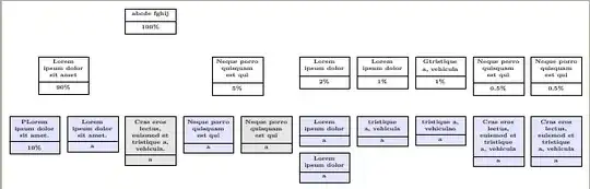
Second result is:


right=<distance> of <ref node>.north, anchor=north. – Qrrbrbirlbel Jan 24 '13 at 04:18below oflines which remain unaligned. I guess what I'm looking for is an invisible horizontal line of nodes to anchor each line to. I'm not sure how I'd produce that though. – Tahnoon Pasha Jan 24 '13 at 04:57at (node1|-node2)to place a node at intersection point between horizontal line through node2 and vertical lines through node1. This case node means node.center, but you could also say(node1.north-|node2.west). – Ignasi Jan 24 '13 at 10:13