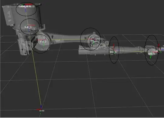
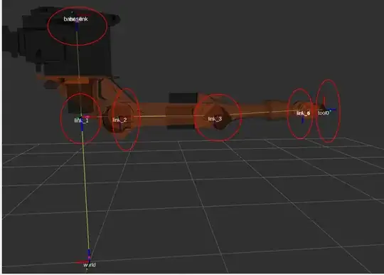
Over here all the links arrows Red, Blue, and Green are pointing in different directions on the other side in Kuka experimental official library is pointing towards the same direction except the tool point.
I believe you created this robot support package yourself, is that correct?
If so: the reason the links in the robot support packages of ros-industrial/kuka_experimental are all oriented the same is because of REP 103: Standard Units of Measure and Coordinate Conventions. In a nutshell: standard frame orientation is: X+ 'forward', Y+ 'to the left', Z+ 'up' (right-handed system).
By using that same convention in the *_macro.xacros in robot support packages, transforms between frames in the same chain, and from objects in the environment to those frames do not result in unexpected rotations. Additionally, adhering to conventions is a good idea, as it will make your own artefacts much easier to reuse by others, who will also be expecting REP 103 compliance.
if I give my robot simulator to go in a particular x,y,z position the same trajectory will be followed by my real robot? Or due to this issue, my robot may mislead and end up with different results?
if by "trajectory" you mean a list of Cartesian poses, then in typical industrial robot use-cases you only define the pose of the Tool Centre-Point, not of any of the intermediate links (typical industrial robots don't give you any direct control over the intermediate links in any case). So as long as you've made sure that whatever you use for TCP frame in your ROS application corresponds to what your real robot has, things should-just-work.
But this all depends on what the parent is of the transform to your TCP frame. If you're using base_link->my_tcp and base_link is not in the correct location wrt your real hw, things will-not-just-work.
Originally posted by gvdhoorn with karma: 86574 on 2021-05-05
This answer was ACCEPTED on the original site
Post score: 1
Original comments
Comment by gvdhoorn on 2021-05-05:
I've written a bit about this in Coordinate Frames for (Serial) Industrial Manipulators, specifically the section about the base frame.
Comment by Ranjit Kathiriya on 2021-05-05:
Thanks! for the answer, my base and link1 are the same for both, but the link I can see my link changing from link 2- link6. I have oriented my tool position same as Kuka experimental by editing macro code. I think this should work out.
Thanks for your detailed understanding of this topic.
Comment by fvd on 2021-05-05:
@gvdhoorn Do you know if there is a convention re. the orientation of TCP frames, e.g. "Positive X points 'forward'" as in the flange frame? REP103 only gives examples for bodies and locations, and this REP199 draft does not mention anything for the application-specific tool frames. I've wondered about this for tools like screw drivers, drills, welding torches etc.
edit: This should probably be a question of its own, but this already has so many relevant links that I'll consider this comment a request for clarification/completeness.
Comment by gvdhoorn on 2021-05-05:
I'd say those conventions would probably come from the domain -- in this case 'traditional' industrial robotics / cnc.
Toolframes of many industrial robots have Z+ forward, of many CnC controls have Z- forward. There's something to say for both.
But there are no requirements for Z to be involved at all. If you'd like a toolframe which has X- "to the front" and it makes sense for your tool, why not.
"This REP 199" does not say anything about toolframes, as it's too dependent on local factors and preference.
Similar to tool0, TCP frames are exempt from following REP-103 in REP-199, precisely because of this.
Comment by gvdhoorn on 2021-05-05:\
I've wondered about this for tools like screw drivers, drills, welding torches etc.
What I've seen is that in my experience, toolframes end up aligned with whatever is:
- the dominant 'plane of work' (not official terminology), and
- the redundant axis
re 1: if you're mostly moving in the XY-plane, and your tool approaches that plane along the Z axis, then having your toolframe defined 'along Z' (whether + or -) makes sense: translating tool up or down is easily modelled as a motion along Z perpendicular to the workpiece.
re 2: for drilling and screwing it doesn't really matter what the orientation along the tool is (it's rotating all the time anyway). So this makes that dof 'redundant', which makes it ideal to align one of the axes of your toolframe along. Rotation would then be 'around' Z, with motions still being mostly in XY-plane. Orientation around Z is not too important, which makes motion planning (even mental) easy to do.
But again: no standards afaik.