With PSTricks:
Method 1 (with Curved Abscissa)

\documentclass[pstricks,border=12pt]{standalone}
\usepackage{pst-eucl}
\addtopsstyle{gridstyle}{gridlabels=0pt,griddots=0}
\begin{document}
\begin{pspicture}[showgrid](-2,-2)(2,2)
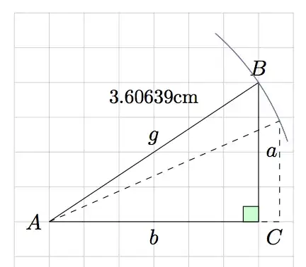
\pstGeonode[PosAngle={180,45,-90}]
(-1.5,-1){A}
(1.5,1){B}
(1.5,-1){C}
\pstRightAngle[RightAngleSize=0.2,fillstyle=solid,fillcolor=green!50]{A}{C}{B}
\pstArcOAB[arcsepB=-1,arcsepA=-2.5]{A}{B}{B}
\pstCurvAbsNode[CurvAbsNeg=true,PointName=none]{A}{B}{D}{\pstDistVal{.75}}
\psline[linestyle=dashed](A)(D)(D|C)(C)
\psset{shortput=nab,labelsep=-3pt}
\ncline{A}{B}^{$g$}
\ncline{B}{C}^{$a$}
\ncline{C}{A}^{$b$}
\end{pspicture}
\end{document}
Method 2 (with PostScript Pyth2 operator)

\documentclass[pstricks,border=12pt]{standalone}
\usepackage{pst-eucl}
\addtopsstyle{gridstyle}{gridlabels=0pt,griddots=0}
\psset{saveNodeCoors}
\begin{document}
\begin{pspicture}[showgrid](-2,-2)(2,2)
    \pstGeonode[PosAngle={180,45,-90}]
        (-1.5,-1){A}
        (1.5,1){B}
        (1.5,-1){C}
    \pstRightAngle[RightAngleSize=0.2,fillstyle=solid,fillcolor=green!50]{A}{C}{B}
        \pstVerb{/Dist {N-A.x N-A.y N-B.x N-B.y Pyth2} def}%
        \pnode[A](!Dist 21 PtoC){D}\psdots(D)
    \psarc[origin={A},arcsep=-1](A){!Dist}{(D)}{(B)}
    \psline[linestyle=dashed](A)(D)(D|C)(C)
    \psset{shortput=nab,labelsep=-3pt}
    \ncline{A}{B}^{$g$}
    \ncline{B}{C}^{$a$}
    \ncline{C}{A}^{$b$}
\end{pspicture}
\end{document}
Method 3 (with rotation)

\documentclass[pstricks,border=12pt]{standalone}
\usepackage{pst-eucl}
\addtopsstyle{gridstyle}{gridlabels=0pt,griddots=0}
\begin{document}
\begin{pspicture}[showgrid](-2,-2)(2,2)
    \pstGeonode[PosAngle={180,45,-90}]
        (-1.5,-1){A}
        (1.5,1){B}
        (1.5,-1){C}
    \pstRightAngle[RightAngleSize=0.2,fillstyle=solid,fillcolor=green!50]{A}{C}{B}
        \pstRotation[PointName=none,RotAngle=-12]{A}{B}[D]
    \pstArcOAB[arcsep=-1]{A}{D}{B}
    \psline[linestyle=dashed](A)(D)(D|C)(C)
    \psset{shortput=nab,labelsep=-3pt}
    \ncline{A}{B}^{$g$}
    \ncline{B}{C}^{$a$}
    \ncline{C}{A}^{$b$}
\end{pspicture}
\end{document}
Method 4 (with intersection)

\documentclass[pstricks,border=12pt]{standalone}
\usepackage{pst-eucl}
\addtopsstyle{gridstyle}{gridlabels=0pt,griddots=0}
\begin{document}
\begin{pspicture}[showgrid](-2,-2)(2,2)
    \pstGeonode[PosAngle={180,45,-90}]
        (-1.5,-1){A}
        (1.5,1){B}
        (1.5,-1){C}
    \pstRightAngle[RightAngleSize=0.2,fillstyle=solid,fillcolor=green!50]{A}{C}{B}
        \pnode[A](1;21){D'}
        \pstInterLC{A}{D'}{A}{B}{E}{D}% E is not used but we have to provide a name for it!
    \pstArcOAB[arcsep=-1]{A}{D}{B}
    \psline[linestyle=dashed](A)(D)(D|C)(C)
    \psset{shortput=nab,labelsep=-3pt}
    \ncline{A}{B}^{$g$}
    \ncline{B}{C}^{$a$}
    \ncline{C}{A}^{$b$}
\end{pspicture}
\end{document}
Red alert: For the sake of simplicity, I left the nodes D in the given methods slightly different. It is not difficult to make them identical.


\draw let \p1=($(B)-(A)$),\n1={veclen(\x1,\y1)},\n2={atan2(\x1,\y1)} in (A) ++(\n2-15:\n1) arc (\n2-15:\n2+15:\n1);– karathan Mar 12 '13 at 12:22\n2to create the arc of the\thetaangle? – karathan Mar 12 '13 at 16:52\thetaat point A using the\n2– karathan Mar 12 '13 at 17:14\n2while it is available. – percusse Mar 12 '13 at 17:24\draw[dashed] (A)-- ($ (A)!1!-10:(B)$) |- (A);. I have seen the manual of pgf but i didn't fully understand the meaning of the!in the code – karathan Mar 18 '13 at 21:40($(Α)!-10:(Β)$)– karathan Mar 18 '13 at 22:20\usetikzlibrary{calc} \begin{tikzpicture} \node (a) at (0,0) {A}; \node (b) at (2,0) {B}; \draw (a) -- ($(a)!0.7!(b)$); \end{tikzpicture}and play with 0.7 with different numbers to see how fraction modifies the length. 1 is the full length 0.5 is the halfway – percusse Mar 18 '13 at 22:34:then do not put!at the right, or I get it wrong? – karathan Mar 18 '13 at 22:49\draw (a) -- ($(a)!0.7!10:(b)$);makes the path rotated 10 degrees after it has been calculated. Start with 0 degrees which is equal to not putting an angle and gradually increase the angle and you'll see what I mean. – percusse Mar 18 '13 at 22:55