5

I'm playing around with intersections to draw an illustration for a lecture about optics. However, I'm having a few issues as the following example shows:

%!TEX encoding = UTF-8 Unicode
%!TEX program = lualatex
\documentclass[11pt,a4paper,fleqn,pdftex]{report}
\usepackage[dvipsnames, table]{xcolor}
\usepackage[utf8]{luainputenc} 
\usepackage[latin,english]{babel}
\usepackage{tikz}
\usetikzlibrary{patterns}
\usetikzlibrary{shapes.geometric}

\begin{document}
    \begin{figure}[!h]
   \centering
   \begin{tikzpicture}
      \coordinate (M2) at (0,3);
      \def\angleM{10}
% >>>>>>>>>>>>>>>>
      \draw[color=Red, thick] (M2) --  (intersection cs: first line={(M2)--++(90 - \angleM:-8)}, second line={(45:-4)--(45:4)}) circle (2pt);
      \draw[color=Red, thick] (intersection cs: first line={(M2)--++(90 - \angleM:-8)}, second line={(45:-4)--(45:4)}) circle (2pt) -- (M2);
% <<<<<<<<<<<<<<<<
      \draw[thick] (M2) ++(1,0) -- ++(-2,0) node[left]{$M_2$};
      \fill[pattern=north east lines] (M2) ++(1,0) rectangle ++(-2,0.2);
      \draw[very thick] (45:-2) -- (45:2);
   \end{tikzpicture}
\end{figure}
\end{document}

In this example, the two lines between % >>>>>… and % <<<<… should draw the same lines, but don't as you can see here:

intersection

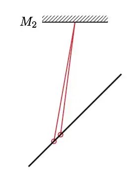
While the instructions are almost the same (only the draw direction differs), the lines don't overlap as they should. What can I do to avoid this?

LaX
  • 516
  • intersection library is very sensitive to rounding errors, that's the problem. – yo' Feb 21 '15 at 19:28
  • @yo' Is there anything I could use instead? – LaX Feb 21 '15 at 19:29
  • compute the points manually? ... I know it sucks. Maybe someone knows what to do better. I unfrotunately do not. – yo' Feb 21 '15 at 19:31
  • @yo' but I want to do the draw multiple times with different parameters and many intersections, so I'll need to find a flexible solution. (This is the experiment I'm drawing: https://en.wikipedia.org/wiki/Michelson–Morley_experiment) – LaX Feb 21 '15 at 19:41
  • 1
    @LaX as a workaround, you can use the intersections library \usetikzlibrary{intersections} and then do \path[name path=line1] (M2)--++(90 - \angleM:-8) [name path=line2] (45:-4)--(45:4); \draw[Red,thick,name intersections={of=line1 and line2}] (intersection-1) -- (M2); it's a bit longer than using the intersection cs, but you won't be depending on rounding problems. – Gonzalo Medina Feb 21 '15 at 21:33
  • @GonzaloMedina That's actually an excellent solution, as all my intersecting lines are already existing paths (mirrors). However, I now have to declare these paths before the intersection, whereas I like to have the mirrors drawn on top of the beams. Is there a kind of layer library I could use for that? – LaX Feb 21 '15 at 22:49
  • @LaX there's the background library exactly for this. Have a look at the PGF manual, Section 109 Layered Graphics. – Gonzalo Medina Feb 21 '15 at 23:28
  • For optical illustrations and setups you might want to have a look at the pst-optexp package. – Christoph Mar 30 '15 at 20:09

1 Answers1

1

This seems to be a rounding problem. This problem and the one discussed in TikZ not computing intersection suggest that there are some problems with the intersection coordinate system (in fact, the PGF manual doesn't mention it and only presents an example of its use).

Anyway, as a workaround, you could load the intersections library and then do

\path
  [name path=line1] (M2) -- ++(90 - \angleM:-8) 
  [name path=line2] (45:-4) -- (45:4); 
\draw[Red,thick,name intersections={of=line1 and line2}] 
  (intersection-1) circle (2pt) -- (M2);

this is just a bit longer than using the intersection cs, but you won't be troubled by different results resulting from rounding problems. A complete example showing both approaches side-by-side:

%!TEX encoding = UTF-8 Unicode
%!TEX program = lualatex
\documentclass[11pt,a4paper,fleqn,pdftex]{report}
\usepackage[dvipsnames, table]{xcolor}
\usepackage[utf8]{luainputenc} 
\usepackage[latin,english]{babel}
\usepackage{tikz}
\usetikzlibrary{patterns}
\usetikzlibrary{shapes.geometric}
\usetikzlibrary{intersections}

\begin{document}

   \begin{tikzpicture}[baseline]
      \coordinate (M2) at (0,3);
      \def\angleM{10}
% >>>>>>>>>>>>>>>>
      \draw[color=Red, thick] (M2) --  (intersection cs: first line={(M2)--++(90 - \angleM:-8)}, second line={(45:-4)--(45:4)}) circle (2pt);
      \draw[color=Red, thick] (intersection cs: first line={(M2)--++(90 - \angleM:-8)}, second line={(45:-4)--(45:4)}) circle (2pt) -- (M2);
% <<<<<<<<<<<<<<<<
      \draw[thick] (M2) ++(1,0) -- ++(-2,0) node[left]{$M_2$};
      \fill[pattern=north east lines] (M2) ++(1,0) rectangle ++(-2,0.2);
      \draw[very thick] (45:-2) -- (45:2);
   \end{tikzpicture}\qquad
%
   \begin{tikzpicture}[baseline]
      \coordinate (M2) at (0,3);
      \def\angleM{10}

      \path
        [name path=line1] (M2) -- ++(90 - \angleM:-8) 
        [name path=line2] (45:-4) -- (45:4); 
      \draw[Red,thick,name intersections={of=line1 and line2}] 
        (intersection-1) circle (2pt) -- (M2);

      \draw[thick] (M2) ++(1,0) -- ++(-2,0) node[left]{$M_2$};
      \fill[pattern=north east lines] (M2) ++(1,0) rectangle ++(-2,0.2);
      \draw[very thick] (45:-2) -- (45:2);
   \end{tikzpicture}

\end{document}

enter image description here

Gonzalo Medina
  • 505,128