The coordinate specification (1,2,3) will eventually be processed by
\pgfpointxyz{1}{2}{3}
You can redefine this macro (locally) to implement a different coordinate system.
To be specific, \pgfpointxyz is a macro that reads three numbers and defines \pgf@x to be the desired x-coordinate and \pgf@y to be the desired y-coordinate. (See pgfcorepoints.code.tex line 852-864 for its original definition.)
In this case, where a coordinate system is well-prepared, you may also do
\def\tikz@parse@splitxyz#1#2#3,#4,{%
    \def\pgfutil@next{\tikz@scan@one@point#1(3d cs:{#2},{#3},{#4})}%
}
See tikz.code.tex line 5415-5417 for its original definition.
By the way, there is already a library called 3d,
you probably want to use a different name other than 3d.
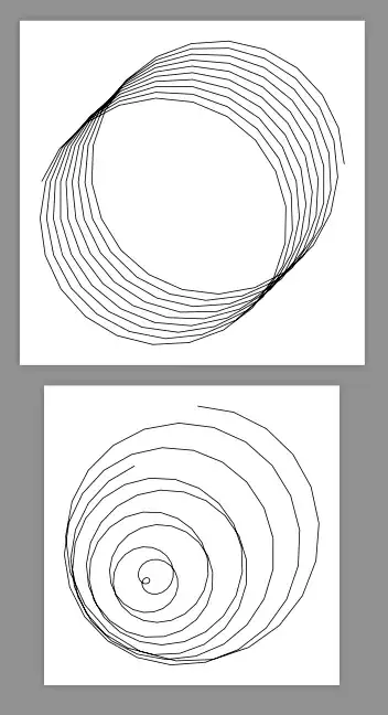
This is a working example. The code of the two tikzpicture are the same. But with different parsers they result in different curves.
\documentclass[border=9,tikz]{standalone}
\usetikzlibrary{3d}
\begin{document}

\makeatletter
\def\tikz@parse@splitxyz#1#2#3,#4,{%
    \def\pgfutil@next{\tikz@scan@one@point#1(xyz cylindrical cs:angle=#2,radius=#3,z=#4)}%
}
\tikz{
    \draw(0,2,0)foreach\i in{1,...,200}{
        --(17*\i,2,\i/80)
    };
}
\def\tikz@parse@splitxyz#1#2#3,#4,{%
    \def\pgfutil@next{\tikz@scan@one@point#1(xyz spherical cs:angle=#2,radius=#3,latitude=#4 r)}%
}
\tikz{
    \draw(0,2,0)foreach\i in{1,...,200}{
        --(17*\i,2,\i/80)
    };
}
Edit log: @Schrödinger's cat notices the changes
of the internal macro name which invalidate my answer.
So I correct it.
