Note that every node needs a (probably empty) label text. So, you always should place a pair of curly braces after every \node (or node) macro.
Now, if you really want to place drawings inside nodes, what you can do is to use pics in combination with path picture.
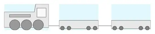
Actually, it might be easier to just use the pics without placing them inside nodes. It is very easy to just place them somewhere using just \pic at (0,0) {truck}; for example. But since I don't know what your aim is eventually, I post this solution:
\documentclass[border=10pt]{standalone}
\usepackage{tikz}
\tikzset{
    truck/.pic={
        \draw[fill=gray!20]
            (-1.5,0.1) rectangle (1.5,0.75);
        \draw[fill=gray]
            (-1.25,0.15) circle[radius=0.15]
            (-0.75,0.15) circle[radius=0.15]
            (0.75,0.15) circle[radius=0.15]
            (1.25,0.15) circle[radius=0.15];
    },
    engine/.pic={
        \draw[fill=gray!20]
            (-1.7,0.2) -- (1.7,0.2) -- (1.7,2) -- (0.7,2)
                -- (0.6,1.4) -- (-1.7,1.4) -- (-1.7,0.2);

        \draw[fill=gray!80]
            (-0.9,0.4) circle[radius=0.4]
            (0,0.4) circle[radius=0.4]
            (0.9,0.4) circle[radius=0.4];
        \draw[fill=gray!50]
            (-1.3,1) rectangle (0.3,1.2);
        \draw[fill=gray!5]
            (0.8,1) rectangle (1.5,1.7);
    }
}
\begin{document}
\begin{tikzpicture}[
        truck/.style={
            minimum width={3cm+0.4pt},
            minimum height={2cm+0.4pt},
            path picture={
                \pic at ([yshift=0.2pt]path picture bounding box.south) {truck};
            },
            yshift=0.67cm
        },
        engine/.style={
            minimum width={3.4cm+0.4pt},
            minimum height={2cm+0.4pt},
            path picture={
                \pic at ([yshift=0.2pt]path picture bounding box.south) {engine};
            },
            yshift=0.67cm
        },
    ]
\draw
    (0,0) node[engine, fill=cyan!10] {}
        -- (4,0) node[truck, fill=cyan!10] {}
        -- (8,0) node[truck, fill=cyan!10] {};

\end{tikzpicture}
\end{document}
Explanation:
First I converted your drawings of the truck and the engine to pics. This is very simple since it is actually just the code you already hat. I only shifted the drawings a bit to the left, so that they are horizontally centered at y = 0. Both drawings sit on the same baseline (at x = 0).
Then, I used the path picture option to create styles for the nodes where I essentially just place the relevant pic so that it becomes the background of the node. It is important here to correctly set the width and height of the node: It should be as wide and as high as the pic plus half of the line width, because otherwise the lines will be clipped at the borders of the node. I aligned the path pictures relative to the bottom of the relevant node using path picture bounding box.south.
I finally shifted the nodes a bit, so that they sit at a reasonable height relative to the connecting line. I shaded the background of the nodes just to make them visible. You may want to remove this shading.
As stated above, a much simpler approach is to only use pics and use the ability to add prefixable coordinates to them (somewhat similar to anchors):
\documentclass[border=10pt]{standalone}
\usepackage{tikz}
\tikzset{
    truck/.pic={
        \draw[fill=gray!20]
            (-1.5,0.1) rectangle (1.5,0.75);
        \draw[fill=gray]
            (-1.25,0.15) circle[radius=0.15]
            (-0.75,0.15) circle[radius=0.15]
            (0.75,0.15) circle[radius=0.15]
            (1.25,0.15) circle[radius=0.15];
        \coordinate (-front) at (-1.5,0.25);
        \coordinate (-back) at (1.5,0.25);
    },
    engine/.pic={
        \draw[fill=gray!20]
            (-1.7,0.2) -- (1.7,0.2) -- (1.7,2) -- (0.7,2)
                -- (0.6,1.4) -- (-1.7,1.4) -- (-1.7,0.2);

        \draw[fill=gray!80]
            (-0.9,0.4) circle[radius=0.4]
            (0,0.4) circle[radius=0.4]
            (0.9,0.4) circle[radius=0.4];
        \draw[fill=gray!50]
            (-1.3,1) rectangle (0.3,1.2);
        \draw[fill=gray!5]
            (0.8,1) rectangle (1.5,1.7);
        \coordinate (-front) at (-1.7,0.25);
        \coordinate (-back) at (1.7,0.25);
    }
}
\begin{document}
\begin{tikzpicture}
\pic (A) at (0,0) {engine};
\pic (B) at (3.5,0) {truck};
\pic (C) at (7,0) {truck};

\draw
    (A-back) -- (B-front)
    (B-back) -- (C-front);


\end{tikzpicture}
\end{document}


node contentsyou can't have anything after the]that closes the options that amongst other sets thenodecontents. The node name or theat (…)needs to come before, i.e.node (A) [truck, above]or needs to be part of the options, e.g.node[truck, above, name=A]. – Qrrbrbirlbel Dec 03 '22 at 00:00