12

I am attempting to make a 3D model of a device defined by a list of {x,y,z} points, digitized from a 2D image. The z coordinate is defined in mma.

What I tried so far:

area = {{0, 452.45658}, {414.75187, 601.63611}, {506.55465, 
    696.71757}, {832.78241, 686.88155}, {936.06054, 
    739.34029}, {1103.27276, 719.66826}, {1155.73149, 
    726.2256}, {1218.02624, 701.63557}, {1281.96032, 
    686.88155}, {1618.02409, 677.04554}, {1740.97425, 
    588.52143}, {2040.97264, 465.57127}, {2077.90455, 
    459.01393}, {2077.90455, 0}, {1581.95871, 0}, {1475.40191, 
    203.2776}, {1301.63235, 608.19345}, {1180.32152, 
    649.17684}, {1163.92817, 667.20953}, {1132.7808, 
    667.20953}, {1073.76472, 660.65219}, {944.25722, 
    673.76687}, {899.99516, 644.25883}, {837.70042, 
    627.86548}, {809.83171, 601.63611}, {809.83171, 
    578.68541}, {609.83279, 111.47481}, {560.65272, 0}, {0, 0}};

area1 = MapThread[Append, {area, ConstantArray[0, Length[area]]}];

area2 = MapThread[Append, {area, ConstantArray[200, Length[area]]}];

Show[Graphics3D[Polygon[area1]], Graphics3D[Polygon[area2]]]

(*This shows top and bottom faces of desired shape, but I want the sides filled in*)

total = Join[area1, area2];

Graphics3D[Polygon[total]]

(*This makes a 3D polygon, but the points are not ordered correctly*)

Graphics3D[
 Polygon[total[[
   FindShortestTour[total] // Flatten // Delete[#, {{1}, {-1}}] &]]]]

(*This reorders the points, but not in the way I want. I don't think there is a way to simply reorder the points in the right way.*)
C. E.
  • 70,533
  • 6
  • 140
  • 264
Peter
  • 133
  • 6

6 Answers6

8
topbottom = Graphics3D[{Opacity[.7], Polygon /@ {area1, area2}}];

sides = Graphics3D[{EdgeForm[], Opacity[.7], 
    Polygon[Partition[Join @@ Transpose[{Join[area1, {First@area1}], 
            Join[area2, {First@area2}]}], 3, 1]]}];

Show[topbottom, sides, ImageSize -> 600]

Mathematica graphics

Or, put everything in a single Graphics3D:

Graphics3D[{Opacity[.7], Polygon /@ {area1, area2}, EdgeForm[], 
  Polygon[Partition[Join @@ Transpose[{Join[area1, {First@area1}], 
       Join[area2, {First@area2}]}], 3, 1]]}, ImageSize -> 600]
(* same picture *)
kglr
  • 394,356
  • 18
  • 477
  • 896
  • Hi All, Thanks kguler, virgil, and others. I used virgil's functionization of kguler's solution, I have numerous funny shapes to "extrude." – Peter Apr 30 '15 at 15:39
7

It think it is nice to know that with latest Computational Geometry it is very simple - just a an orthogonal RegionProduct.

R2 = MeshRegion[area, Polygon[Range[Length[area]]]];
R3 = RegionProduct[R2, Line[{{0.}, {500.}}]];

Now you can for example:

RegionMeasure[R3]

or

DiscretizeRegion[R3]

enter image description here

Vitaliy Kaurov
  • 73,078
  • 9
  • 204
  • 355
4

I found out that this is basically the same as @kguler's answer, but I want to mention that this can be easily functionized. Borrowing from this question, we can define something similar:

Options[Extrude] = Join[
   Options[Graphics3D], {Closed -> True, Capped -> True, Color -> Orange}];

Extrude[points_, {zmin_, zmax_}, opts : OptionsPattern[]] := Module[{pts, tube, caps},
   If[OptionValue[Closed], pts = points~Join~{First@points}];
   tube = Polygon[
     Partition[
      Join @@ Transpose[points /. {x_, y_} -> {x, y, #} & /@ {zmin, zmax}], 3, 1]];
   If[OptionValue[Closed] && OptionValue[Capped], 
    caps = Polygon[points /. {x_, y_} -> {x, y, #}] & /@ {zmin, zmax};
    tube = Flatten@{tube, caps}, 
    tube = {tube}];
   Graphics3D[Flatten@{EdgeForm[None], OptionValue[Color], #} & /@ tube, 
    FilterRules[{opts}, Options[Graphics3D]]]
  ];

Then, apply it to the points area thusly:

Extrude[area, {0, 200}, Color -> Red]

extrude

Virgil
  • 3,437
  • 16
  • 27
4

You could simply use the function prism from my answer to How can this texture be inserted in the beginning and the end of cylinder?.

The advantage is that it also allows you to add textures (optionally), and has vertex normals built in so that the shape appears smooth. Here it is just for fun:

l = {{"Directional", Red, ImageScaled[{2, 2, 2}]},
   {"Directional", Green, ImageScaled[{-2, 2, 2}]},
   {"Directional", Blue, ImageScaled[{-2, -2, 2}]}};

Graphics3D[{EdgeForm[], FaceForm[Opacity[.5]], prism[area, 500]}, Boxed -> True, Axes -> True, Lighting -> l, SphericalRegion -> True]

shape

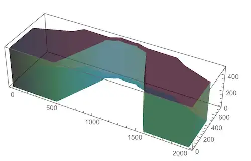
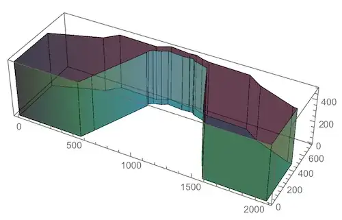
I set the shape to have no edges, so as to emphasize the smoothness. But if you want to see the striations on the side walls, just omit EdgeForm[] above. The result will then be this:

edges

Edit

The original version of the function prism determined vertex normals based on the assumption that the shape is really a cylinder, or at least convex. That doesn't give very good estimates of all the appropriate vertex normals in this case, so it prompted me to look for a more accurate way of determining a set of vertex normals that still do the job of smoothly interpolating between adjacent face normals.

Here is what I came up with:

prism[pts_List, h_] := 
 Module[{bottoms, tops, surfacePoints, sidePoints, n}, 
  surfacePoints = 
   Table[Map[PadRight[#, 3, height] &, pts], {height, {0, h}}];
  {bottoms, tops} = {Most[#], Rest[#]} &@surfacePoints;
  sidePoints = 
   Flatten[{bottoms, RotateLeft[bottoms, {0, 1}], 
     RotateLeft[tops, {0, 1}], tops}, {{2, 3}, {1}}];
  n = Length[sidePoints];
  MapThread[Polygon[#1,
     VertexNormals -> #2,
     VertexTextureCoordinates -> #3] &, {Join[sidePoints, 
     surfacePoints], 
    Join[normals[sidePoints], 
     Map[({0, 0, h/2}) &, surfacePoints, {2}]], 
    Join[Table[{{i/n, 0}, {(i + 1)/n, 0}, {(i + 1)/n, 1}, {i/n, 
        1}}, {i, 0, n - 1}], {#, #} &[Rescale[pts, {-h, h}/2]]]}]]

normals[s_] := Module[{faceN, faceLeft, faceRight}, faceN = Map[Cross @@ Differences[#[[1 ;; 3]]] &, s]; faceLeft = RotateLeft[faceN]; faceRight = RotateRight[faceN]; MapThread[{#1 + #2, #1 + #3, #1 + #3, #1 + #2} &, {faceN, faceRight, faceLeft}] ]

Manipulate[ Graphics3D[{EdgeForm[], FaceForm[Opacity[.5]], GeometricTransformation[prism[area, 500], Composition[ RotationTransform[θ, {0, 0, 1}], TranslationTransform[{-1000, -500, 0}]]]}, Boxed -> False, Axes -> False, ImageSize -> 600, Lighting -> l, PlotRange -> {{-1200, 1200}, {-1200, 1200}, {-10, 510}}], {θ, 0, 2 Pi} ]

vertexnormals

In the VertexNormals option, prism now calls the function normals which takes a list of polygon face quads and calculates for each vertex what the normals of adjacent faces are. Then it just adds those normals as a way to produce an interpolating average that makes the side walls look smooth. For the top and bottom of the prism, I chose a constant vertical normal (it doesn't even change direction because that is taken care of by the fact that the polygon orientation is opposite on top and bottom).

Having a smooth side wall may or may not be what the question is after - but since this is the main point of my answer, I decided to expand on the discussion of VertexNormals for the sake of completeness.

Jens
  • 97,245
  • 7
  • 213
  • 499
2

Another way with rectangular polygons on the sides:

bottom = PadRight[area, {Automatic, 3}, 0];
top = PadRight[area, {Automatic, 3}, 400];
Graphics3D[{Opacity[0.7], EdgeForm[],
  Polygon[Join[
    {bottom, top},
    Join[
     Partition[bottom, 2, 1, 1],
     RotateLeft@Reverse@Partition[top // Reverse, 2, 1, 1],
     2]
    ]]
  }
 ]

Mathematica graphics

Michael E2
  • 235,386
  • 17
  • 334
  • 747
0
area = {{0, 452.45658}, {414.75187, 601.63611}, {506.55465, 
    696.71757}, {832.78241, 686.88155}, {936.06054, 
    739.34029}, {1103.27276, 719.66826}, {1155.73149, 
    726.2256}, {1218.02624, 701.63557}, {1281.96032, 
    686.88155}, {1618.02409, 677.04554}, {1740.97425, 
    588.52143}, {2040.97264, 465.57127}, {2077.90455, 
    459.01393}, {2077.90455, 0}, {1581.95871, 0}, {1475.40191, 
    203.2776}, {1301.63235, 608.19345}, {1180.32152, 
    649.17684}, {1163.92817, 667.20953}, {1132.7808, 
    667.20953}, {1073.76472, 660.65219}, {944.25722, 
    673.76687}, {899.99516, 644.25883}, {837.70042, 
    627.86548}, {809.83171, 601.63611}, {809.83171, 
    578.68541}, {609.83279, 111.47481}, {560.65272, 0}, {0, 0}};
area3D = Table[{area[[i, 1]], area[[i, 2]], j}, 
    {i, Length[area]}, {j, 0, 500, 30}];

   Graphics3D[{Line /@ area3D, Line /@ Transpose[area3D], 
   Polygon[Transpose[area3D]]}]

enter image description here

David G. Stork
  • 41,180
  • 3
  • 34
  • 96